2
2
2-10
2-10
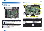
Technical Explanation > Main Controller > Overview > Main controller PCB
Technical Explanation > Main Controller > Overview > Main controller PCB
Main Controller
Overview
■
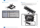
Configuration / Function
HDD
Main Controller PCB
TPM PCB
Flash PCB
USB I/F
Item
Function
Main Controller PCB System Control/Memory Control/Printer Output Image Processing Control,
Reader Image Input Processing, Card Reader Connection I/F, Fax Image
Processing, USB Extension HUB Connection I/F
RAM
Temporarily storage of image data:
Capacity of 1 GB (for controller control) + 1 GB (for image processing)
USB port USB2.0 Device I/F, USB2.0 Host I/F
SRAM
none
Hard disk
2.5-inch SATA I/F Standard: 250 GB (215 GB usable area), address list,
security information (password, certificate), image data, preferences
Flash PCB
Storage of system software: 2 GB
TPM PCB
Generation and storage of the encryption key.
(Only when Management Settings > Data Management > TPM Settings is
"On". Default: Off)
F-2-12
T-2-7
■
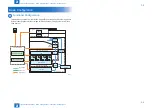
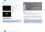
Main controller PCB
J17
USB(D)
LAN
USB(H)
TPM
FAN
FAX
Laser
FAX
FAX
UI
DEVICE
PORT
Voice
Internal I/F
External I/F
HDD ADF
ADF
Reader
HDD
FLASH
Memory
J6
J4
J28
J27
J19
J16
J7
J8
J3
J5
J15
J14
J32
J25 J20
J18
J22
J29 J35
J23
J38 J36 J33
J37
J40
J10
J24
J30
Image Data
Analyzer PCB
CC-VI CARD
DC Controller
Low voltage
power supply
Main power
supply
No.
Functions and specifications
No
Functions and specifications
J3
USB I/F (Device)
J20/J25 Low-voltage Power Supply PCB
J4
Control Panel I/F
J23/J29 Hard disk
J5
USB I/F (Host)
J24
Counter Memory PCB
J6
USB Device Port
J27/J30 Fax (1-Line)
J7
LAN I/F
J28
Image Data Analyzer PCB
J8
TPM PCB
J32
Main Power Supply Switch
J10
Flash PCB
J33
Scanner Unit
J14
Serial Interface Kit
J35/J38 ADF Driver PCB
Copy Card Reader
J36
Scanner Motor
J15
Copy Control Interface Kit I/F
J37
Scanner Unit HP Sensor
J16
Fax (2-Line)
Copyboard Cover Open/Close Sensor
(Front/Rear)
J17
Voice Operation Kit
Original Size Sensor (AB/INCH)
J18
DC Controller PCB
J40
Controller Fan
F-2-13
T-2-8


