background image

ZC3500050

– 6 –

4030-7775-02

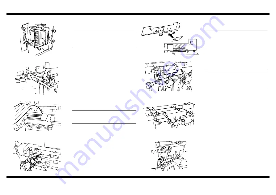
Installing the Hard Disk Drive to the Copier

1. Reinstall the Mechanical Board Cover to the 

copier (five screws).

NOTE

Use care not to allow the harness on the 
right of the Mechanical Board Cover to be 
wedged in the mechanism.

4599U039AA

2. Tidy up the harness on the copier side using 

wiring saddles.

4599U041AB

3. Connect the Flat Cable of the Hard Disk 

Drive to CN4 of the Network Interface Card.

NOTE

Make sure that the Flat Cable does not 
twist when connected.

4599U035AA

4. Install the connector mounting bracket (one 

black screw).

4599U032AA

4599U044AA

5. Affix the Protective Film furnished with the 

Hard Disk Drive to the reinforcement plate.

NOTE

Clean the surface of the reinforcement 
plate, to which the Protective Film is to be 
affixed, with alcohol.

Reference Position for Affixing Film

4599U042AA

6. Install the reinforcement plate (four black 

screws).

NOTE

Use care not to allow the Flat Cable and 
Harness of the Hard Disk Drive to be 
caught in the mechanism.

4599U036AA

7. Install the Network Interface Card cover (six 

black screws).

4599U017AA

8. Tidy up the harness of the copier into the 

wiring saddle.

4599U016AA

Summary of Contents for im2020

Page 1: ...SETUP INSTRUCTIONS im2020 2520 3520 2520f Copier and Peripherals...

Page 2: ...BLANK PAGE...

Page 3: ...Desk 550 x 2 9218 Large Capacity Cassette 2700 sheets 9219 Duplex Unit 9219000000 Reversing Unit ZC3500050 Hard Disk Drive ZC3500060 Output Bin ZC3500070 Job Separator ZC3500080 Printer Controller PC...

Page 4: ...BLANK PAGE...

Page 5: ...GMT Standard Time GMT Atlantic Eastern Central Mountain Pacific Alaska Hawaii 4 5 6 7 8 9 10 Note Subtract an hour for Daylight Savings Time...

Page 6: ...BLANK PAGE...

Page 7: ...TRUCTIONS 9217 2 Way Paper Feed Cabinet NOTES Before setting up be sure to unplug the power cord of the machine Keep all packing materials out of the reach of children 4348 7747 02 fm Page 0 Wednesday...

Page 8: ...n follow the instructions given in the Setup Instructions of the corresponding option to ensure the option is set up correctly PCN Description 9210 RADF 9211 Multiposition Stapling Finisher 9212 Punch...

Page 9: ...ifferent parts of the Paper Feed Cabinet 1 Fixing Leg 4 2 Fixing Leg Cover 4 3 Fixing Bracket 4 4 Shoulder Screw 4 5 Screw 9646 0408 12 6 Paper Size Label 1 7 Setup Instructions this manual 1 4348U004...

Page 10: ...paper take up section of the copier 4348U017AB 3 Peel off the tape that fixes the Paper Feed Cabinet hookup harness in position 4 Connect the two connectors of the Paper Feed Cabinet hookup harness to...

Page 11: ...uded Portions of the cover shown by the arrows into the Fixing Leg 4348U023AD 4 Install the Fixing Legs at two locations in the rear shown in the illustration six screws 5 Install the Fixing Leg Cover...

Page 12: ...Print screen 4348P015CA 7 Touch 3rd Drawer This highlights the 3rd Drawer key 4348P017CA 8 Press the Start key on the control panel The copier will produce an output of a test print 4002O280CB 9 Measu...

Page 13: ...e adjustment perform the following procedure paper reference position adjust ment 2 1 Slide out the drawer and unload paper from it 2 Loosen the three screws at the center of the Paper Lifting Plate 4...

Page 14: ...BLANK PAGE...

Page 15: ...4348 7743 03 SETUP INSTRUCTIONS 9218 Large Capacity Cabinet NOTES Before setting up be sure to unplug the power cord of the machine Keep all packing materials out of the reach of children...

Page 16: ...er 9212 Punch Unit 9214 Saddle Stitch Finisher 9216 Plain Stand 9217 Copy Desk 550 x 2 9218 Large Capacity Cassette 2700 sheets 9219 Duplex Unit 9219000000 Reversing Unit ZC3500050 Hard Disk Drive ZC3...

Page 17: ...peel off the tape that fixes the Large Capacity Cabinet hookup harness in position until the copier is attached to the Large Capacity Cabinet 1 Fixing Leg 4 2 Fixing Leg Cover 4 3 Fixing Bracket 4 4...

Page 18: ...per take up section of the copier 4348U017AB 3 Peel off the tape that fixes the Large Capacity Cabinet hookup harness in position 4 Connect the two connectors of the Large Capacity Cabinet hookup harn...

Page 19: ...llustration 2 Pieces NOTES Insert the Fixing Leg Covers in the direc tion shown by arrow until they click into position Insert the Protruded Portions of the cover shown by the arrows into the Fixing L...

Page 20: ...e key This highlights the A4 paper size key 5 Touch END on the LCC Paper Size screen 4348P013CA 1 Call the Tech Rep Mode to the screen See the Service Manual for the procedure 4348P005CB 2 Follow thes...

Page 21: ...e specified range press the Panel Reset key to recall the Basic screen 10 If the measured width A falls outside the specified range perform the following procedure to adjust the paper reference positi...

Page 22: ...f width A is smaller than the specified value turn screw D clockwise 4002U105AA 4 Let the copier produce another test print and check for the good paper reference position 5 Make the adjustment until...

Page 23: ...4030 7744 02 SETUP INSTRUCTIONS im2020 im2520 im3520 NOTES Keep all packing materials out of the reach of children Before setting up be sure to unplug the power cord of the machine Copiers...

Page 24: ...isher 9212 Punch Unit 9214 Saddle Stitch Finisher 9216 Plain Stand 9217 Copy Desk 550 x 2 9218 Large Capacity Cassette 2700 sheets 9219 Duplex Unit 9219000000 Reversing Unit ZC3500050 Hard Disk Drive...

Page 25: ...7 Power Cord 1 8 Tray Label 1 9 Scanner Lock Lever Seal 1 The Ornamental Cover and Ornamental Cover Mounting Screw are used when a paper source option is mounted See the Setup Instructions for the co...

Page 26: ...oth sides of the PC Drum Unit take out the PC Drum Unit NOTE Do not touch or scratch the PC Drum Cover the PC Drum Unit which has been removed with a protective cloth or similar tool 4 Slide out the d...

Page 27: ...lver screws each on the right and left sides NOTE Use care not to touch or scratch the PC Drum 6 Ready a packet of starter and cut off one corner of the aluminum packet with scissors 4030U012AA 7 Whil...

Page 28: ...Call the Tech Rep Mode to the screen For the procedure see the Service Manual 2 Select functions in this order Tech Rep Mode Counter PM 3 Using the Clear key clear PC Life and then IC Life 4 Touch END...

Page 29: ...the Toner Bottle well about five times in the vertical direction Then turn it over and repeat the same procedure 1166O095AA 3 Open the Front Door and slide the Toner Hopper out of the copier 4030U018A...

Page 30: ...d the drawers with paper 4030U025AB 1 Attach the Operator s Manual Holder to the back surface of the copier 4030U024AA 1 Call the Initial Mode to the screen For the procedure see the Service Manual 40...

Page 31: ...9U002AA 4599U003AA 9654 4599U004AA 1 Remove the Rear Upper Cover and Hinge Covers three screws 4599U005AB 2 Install the Hinge Covers Right and Left included in the kit five screws 3 Reinstall the Rear...

Page 32: ...BLANK PAGE...

Page 33: ...4032 7744 02 SETUP INSTRUCTIONS im2520f Copier NOTES Keep all packing materials out of the reach of children Before setting up be sure to unplug the power cord of the machine...

Page 34: ...212 Punch Unit 9214 Saddle Stitch Finisher 9216 Plain Stand 9217 Copy Desk 550 x 2 9218 Large Capacity Cassette 2700 sheets 9219 Duplex Unit 9219000000 Reversing Unit ZC3500050 Hard Disk Drive ZC35000...

Page 35: ...ay Label 1 10 Scanner Lock Lever Seal 1 11 Warranty Card U S A areas only 1 12 Telephone Cable 1 The Ornamental Cover and Ornamental Cover Mounting Screw are used when a paper source option is mounted...

Page 36: ...es of the PC Drum Unit take out the PC Drum Unit NOTE Do not touch or scratch the PC Drum Cover the PC Drum Unit which has been removed with a protective cloth or similar tool 4 Slide out the drawer a...

Page 37: ...rews each on the right and left sides NOTE Use care not to touch or scratch the PC Drum 6 Ready a packet of starter and cut off one corner of the aluminum packet with scissors 4030U012AA 7 While turni...

Page 38: ...e to the screen For the procedure see the Service Manual 2 Select functions in this order Tech Rep Mode Counter PM 3 Using the Clear key clear PC Life IC Life and then Developer 4 Touch END 5 Press th...

Page 39: ...ner Bottle well about five times in the vertical direction Then turn it over and repeat the same procedure 1166O095AA 3 Open the Front Door and slide the Toner Hopper out of the copier 4030U018AA 4 Op...

Page 40: ...of the copier 4030U024AA 1 Call the Tech Rep Mode to the screen For the procedure see the Service Manual 2 Select Country Set 3 Select the corresponding to your country and then END 4 Touch END 5 Tou...

Page 41: ...A 4599U003AA 9654 4599U004AA 1 Remove the Rear Upper Cover and Hinge Covers three screws 4599U005AB 2 Install the Hinge Covers Right and Left included in the kit five screws 3 Reinstall the Rear Upper...

Page 42: ...BLANK PAGE...

Page 43: ...4344 7741 01 SETUP INSTRUCTIONS 9210 Duplexing Document Feeder NOTES Before setting up be sure to unplug the power cord of the machine Keep all packing materials out of the reach of children...

Page 44: ...ng Unit ZC3500050 Hard Disk Drive ZC3500060 Output Bin ZC3500070 Job Separator ZC3500080 Printer Controller PCL6 ZC3500090 Network Interface Card ZC3500100 Parallel Port ZC3500110 Network Scan Kit ZC3...

Page 45: ...hipping preservatives and remove the protective vinyl bag of the hookup cord 4344U004AA 1 Install the two Shoulder Screws furnished with the Duplexing Document Feeder to the hinge mounting portion NOT...

Page 46: ...nector on the copier side 4344U011AA 6 Fit the hookup harness into the hook on the copier 4344U012AA 2 Loosen the nut on the upper side of the left hinge as viewed from the control panel side by turni...

Page 47: ...e a clearance of 0 5 mm or less when the Duplexing Document Feeder is pressed in the direction of the arrow If the clearance is more than 0 5 mm loosen the nut on the right hinge as viewed from the co...

Page 48: ...ew which has been loosened in step 5 1 Prepare a test chart A3 or 11 17 as shown Draw a 270 mm long straight reference line in the crosswise direction A CD Draw a 390 mm long straight reference line i...

Page 49: ...ier key of CD or FD 4344P002CA 6 Make the Zoom Adjustment A CD B FD If the line is longer than the specifications adjust toward the reduction side If the line is shorter than the specifications adjust...

Page 50: ...a full size copy 4344U021AA 3 Check that the margins reproduced on the copy meet the following specifications Margin Registration Specifications Width A 20 2 0 mm Width B 20 3 0 mm If the margins repr...

Page 51: ...ent Pad pressed up against the Original Length Scale place it on the Original Glass so that its left edge is 0 5 to 1 0 mm away from the Original Width Scale 4344U013AA 0 mm 0 5 to 1 mm 3 Peel off the...

Page 52: ...BLANK PAGE...

Page 53: ...Duplex Unit NOTES Before setting up be sure to unplug the power cord of the machine Keep all packing materials out of the reach of children When the Duplex unit is installed it is necessary to install...

Page 54: ...Punch Unit 9214 Saddle Stitch Finisher 9216 Plain Stand 9217 Copy Desk 550 x 2 9218 Large Capacity Cassette 2700 sheets 9219 Duplex Unit 9219000000 Reversing Unit ZC3500050 Hard Disk Drive ZC3500060...

Page 55: ...1 4349U012AA 2 3 1 4346U032AA 4346U035AA 1 Remove four screws from the Right Door of the copier 2 Remove the cover of the Right Door of the copier one screw 4346U014AB 3 Remove the screws from the Up...

Page 56: ...hanisms Make a positive engagement of the rib of the Duplex Unit with the round hole in the Right Door of the copier If the rib is not in place there will be a clearance at the portion indicated by th...

Page 57: ...ith the Duplex Unit in position NOTE When replacing the coil spring keep the Right Door of the copier closed 4346U004AA 6 Reinstall the metal plate cover which has been removed in step 4 six screws NO...

Page 58: ...4348P009CA 6 Touch Test Print to display the Test Print screen 4348P015CA 7 Touch Duplex This highlights the Duplex key 4348P017CA 8 Press the Start key on the control panel The copier will produce a...

Page 59: ...the Clear C key and using the 10 Key Pad change the setting value as detailed below If width A is greater than the specified value e g 1 0 mm enter 1 0 If width A is smaller than the specified value...

Page 60: ...BLANK PAGE...

Page 61: ...4526 7741 02 SETUP INSTRUCTIONS 9219000000 Switchback Reversing Unit NOTES Before setting up be sure to unplug the power cord of the machine Keep all packing materials out of the reach of children...

Page 62: ...Unit 9214 Saddle Stitch Finisher 9216 Plain Stand 9217 Copy Desk 550 x 2 9218 Large Capacity Cassette 2700 sheets 9219 Duplex Unit 9219000000 Reversing Unit ZC3500050 Hard Disk Drive ZC3500060 Output...

Page 63: ...ng Unit 1 Tray 1 2 Upper Switchback Unit 1 3 Lower Switchback Unit 1 4 Shoulder Screw 3 mm 2 5 Screw 9733 0308 13 2 6 Setup Instructions this manual 1 4625U004AA 4625U002AA 4625U001AA 4025U059AA 4625U...

Page 64: ...ing Unit fixing screws 4625U010AA 4625U012AA 4625U013AA 1 Remove one screw from the Fusing Cover 2 Unhook the hooks at three places on the backside of the cover and remove the cover 4625U014AA 3 Remov...

Page 65: ...per Switchback Unit are positively fitted into the positioning holes in the upper surface of the Fusing Unit Make sure that the screws loosened on the copier side are properly located in the positioni...

Page 66: ...one screw This is the Column Support Cover that has been removed in step 4 on p 2 4625U020AA 2 Install the Column Support Cover on the control panel side one screw 4625U019AB 3 Install the Upper Side...

Page 67: ...4347 7741 02 SETUP INSTRUCTIONS ZC3500070 Job Separator NOTES Before setting up be sure to unplug the power cord of the machine Keep all packing materials out of the reach of children...

Page 68: ...r 9212 Punch Unit 9214 Saddle Stitch Finisher 9216 Plain Stand 9217 Copy Desk 550 x 2 9218 Large Capacity Cassette 2700 sheets 9219 Duplex Unit 9219000000 Reversing Unit ZC3500050 Hard Disk Drive ZC35...

Page 69: ...equipped with a Switchback Unit 1 Tray 1 2 Sensor Unit 1 3 Screw A 3 8 mm 3 4 Screw B 3 8 mm 1 5 Setup Instructions this manual 1 4347U002AA 4347U003AB 9654 9739 1 2 3 4 5 1 Open the Right Door 4346U0...

Page 70: ...7AA 8 Remove the Tray 4347U008AA 9 Remove the cover two screws 4347U009AA 10 Press the Sensor Unit up against the Switchback Unit and secure the Sensor Unit using Screws A two screws NOTE Do not hold...

Page 71: ...rews 4347U013AA 16 Connect the connectors 4347U014AB 17 Reinstall the covers that have been removed in steps 2 and 3 three screws 18 Close the Right Door 19 Install the Tray Fit the Tray into the cuto...

Page 72: ...BLANK PAGE...

Page 73: ...4349 7741 02 SETUP INSTRUCTIONS 9211 Built in Finisher NOTES Before setting up be sure to unplug the power cord of the machine Keep all packing materials out of the reach of children...

Page 74: ...12 Punch Unit 9214 Saddle Stitch Finisher 9216 Plain Stand 9217 Copy Desk 550 x 2 9218 Large Capacity Cassette 2700 sheets 9219 Duplex Unit 9219000000 Reversing Unit ZC3500050 Hard Disk Drive ZC350006...

Page 75: ...her Unit out of the box NEVER hold onto part A 1 Finisher Unit 1 2 Tray Unit 1 3 Front Cover 1 4 Secondary Cover 1 5 Exit Tray Upper 1 6 Exit Tray Lower 1 7 Retaining Plate 1 8 E ring 1 9 Screw A 4 8...

Page 76: ...ket of the Finisher Unit ten screws 4349U020AB Screw 2 Screw 1 3 Remove the protective tape from the Staple Unit 4349U049AA 4 Screw screws 1 and 2 which have been unscrewed from the fixing bracket in...

Page 77: ...Holding the positions indicated by the arrows in the illustration place the Finisher Unit onto the rail of the copier 4349U026AC Rail 7 Slide the Finisher Unit all the way back into the copier 4349U0...

Page 78: ...he Finisher Unit to the right or left as necessary one screw 11 After the adjustment has been made tighten the adjusting screw 4349U029AC 4349U031AA 4349U030AA Paddle NG OK 3 Mount the Tray Unit onto...

Page 79: ...ance between the Misfeed Clearing Dial and Secondary Cover 4349U036AC 9 Using Screw D secure the Secondary Cover one screw 4349U037AA 10 Install the Front Cover to the copier 4349U055AA 11 Close the F...

Page 80: ...nd and the Retaining Plate to the Secondary Cover one screw 17 Fit the label back to the Front Cover 18 Close the Front Cover 4349U041AB 19 Fit the upper and lower Exit Trays and secure them in positi...

Page 81: ...4512 7741 02 SETUP INSTRUCTIONS 9212 Punch Kit NOTES Before setting up be sure to unplug the power cord of the machine Keep all packing materials out of the reach of children 4512 7741 02 fm 0...

Page 82: ...nisher 9212 Punch Unit 9214 Saddle Stitch Finisher 9216 Plain Stand 9217 Copy Desk 550 x 2 9218 Large Capacity Cassette 2700 sheets 9219 Duplex Unit 9219000000 Reversing Unit ZC3500050 Hard Disk Drive...

Page 83: ...1 3 Punch Box 1 4 Flat Spring 1 5 Label 1 6 Screw 3 6 mm 3 7 Setup Instructions this manual 1 4512U001AA 4512U003AA 4512U004AA 9735 4512U002AA 4512U005AA 4 3 6 5 7 1 2 1 Remove the fixing brackets of...

Page 84: ...its in the cover 9 Slightly press the Sensor Unit in the direction shown by the arrow 4512U012AC 1 2 3 10 Withdraw the connector of the Sensor Unit through the hole shown in the illustration 11 Open t...

Page 85: ...Pass the harness of the Punch Unit through cord clamps and route it tidily 4512U018AA 21 Connect the connectors 4512U019AA 22 Reinstall the reinforcement plate that has been removed in step 4 two scr...

Page 86: ...les are not aligned with each other loosen the adjusting screw one screw 4 Holding the upper part of the motor section move the Punch Unit to the front or rear as necessary 5 After the adjustment has...

Page 87: ...inisher NOTES Before setting up be sure to unplug the power cord of the machine Keep all packing materials out of the reach of children When the Duplex unit is installed it is necessary to install the...

Page 88: ...ultiposition Stapling Finisher 9212 Punch Unit 9214 Saddle Stitch Finisher 9216 Plain Stand 9217 Copy Desk 550 x 2 9218 Large Capacity Cassette 2700 sheets 9219 Duplex Unit 9219000000 Reversing Unit Z...

Page 89: ...Creasing Unit Adjusting Plate 1 9 Harness 1 10 Mounting Bracket Cover 1 11 Screw A 3 6 mm 2 12 Screw B 3 8 mm 2 13 Screw C 4 8 mm 10 14 Shoulder Screw A 1 15 Shoulder Screw B 2 16 Setup Instructions...

Page 90: ...shipping carton and remove the protective tape and cushioning materials Installing the Creasing Unit 4511U015AB 4511U016AA Saddle Unit Creasing Unit Exit Tray 4511U017AA 1 Remove the Finisher NOTE For...

Page 91: ...sing Unit and temporarily secure the unit by tightening Screw A 1 screw only temporarily 4511U020AB 7 Secure the rear end of the Creasing Unit using Shoulder Screw A 1 screw NOTE No clearance is allow...

Page 92: ...Mounting Holder See step 5 that follows 4511U025AB Hole 3 Move the Shutter up and down Release the Shutter from a higher position to check to ensure that the Shutter falls by its own weight 4 If the S...

Page 93: ...8 2 screws each 4511U029AA 13 Reinstall the Exit Tray mounting holder left which has been removed in step 7 1 screw NOTE Install the holder at a level one step lower than where it was removed in step...

Page 94: ...hten the right screw and then securely tighten the left screw 4511U033AB Right Left 20 Open the Saddle Unit 21 Using Screw C secure the Saddle Unit to the Mounting Bracket Right 1 screw 4511U036AA 22...

Page 95: ...ons as follows User s Choice 5 6 Crease Center Staple Crease 4511U039CA If the crease deviates as shown on the left 10 Fold the copy fed out along the crease 11 Check the crease for deviation Measure...

Page 96: ...the functions as follows User s Choice 5 6 Crease Center Staple Center Staple 4511U039CA If the Staple positions deviate as shown on the left 25 Fold the copy fed out along the crease 26 Check the sta...

Page 97: ...4030 7772 02 SETUP INSTRUCTIONS ZC3500060 Output Bin NOTES Before setting up be sure to unplug the power cord of the machine Keep all packing materials out of the reach of children 4030 7772 02 fm 0...

Page 98: ...Finisher 9212 Punch Unit 9214 Saddle Stitch Finisher 9216 Plain Stand 9217 Copy Desk 550 x 2 9218 Large Capacity Cassette 2700 sheets 9219 Duplex Unit 9219000000 Reversing Unit ZC3500050 Hard Disk Dri...

Page 99: ...re the Exit Tray Mounting Holder Right and Exit Tray Mounting Holder Left one screw each 4349U002AB 2 Fit the Exit Tray 3 Secure the Exit Tray using Screws A two screws 4349U003AA 4 Loosen the screw s...

Page 100: ...re the Exit Tray Mounting Holder Right and Exit Tray Mounting Holder Left one screw each 4349U005AC 2 Fit the Exit Tray 3 Secure the Exit Tray using Screws A two screws 4349U006AC 4 Loosen the screws...

Page 101: ...her 4349U054AA 9 Reinstall the Secondary Cover two screws NOTE Make sure that there is a uniform clearance between the Misfeed Clearing Dial and Secondary Cover 4349U036AC 10 Reinstall the Secondary C...

Page 102: ...BLANK PAGE...

Page 103: ...SETUP OF MACHINE AND INSPECTION PROCEDURES 1 Setup of machine No change is needed 2 Inspection procedures Make sure that the volume of memory was increased 1 Select SERVICE MODE 2 Touch System Input t...

Page 104: ......

Page 105: ...e memory chips from damage NOTE Disconnecting the Ni MH battery cable from CN3 on the MFB3 circuit board cuts off the power supply from the Ni MH battery to the added memory In the worst case failure...

Page 106: ...xpansion slot 2 CN5 on the printed circuit board assembly s MFB3 cir cuit board NOTE Do not touch the terminals of the circuit board with your bare hands Making sure that the notch in the circuit boar...

Page 107: ...rinter Circuit Board 32 MB ZC3500080 only 2 Printer Circuit Board 128 MB ZC3500130 only 3 CompactFlash Card ZC3500130 only 4 Printer Controller Quick Guide ZC3500080 ZC3500130 5 Printer Driver CD ROM...

Page 108: ...formation 5 Reassembly Perform the disassembly steps in reverse to reassemble NOTE Make sure that plugs are oriented correctly when connecting cables Tighten screws so the spacing between adjoining co...

Page 109: ...13 7746 02 ND 100096 E INSTALLATION GUIDE Network Interface Card ZC3500090 NOTE Before setting up be sure to unplug the power cord of the machine Keep all packing materials out of the reach of childre...

Page 110: ...arranty Card Only U S A and Canada Users 1 Printer Controller ZC3500130 1 Printer Memory Circuit Board 128 MB 1 2 CompactFlash card 1 3 Printer Driver CD ROM 1 4 Printer Controller Quick Guide 1 5 War...

Page 111: ...ZC3500080 or ZC3500130 Network Scan Kit ZC3500110 and Internet Fax Network Scan Kit ZC3500120 1 Removing the outer covers and plates 1 Remove the rear cover Remove the 3 screws at the back of the copi...

Page 112: ...panel 13 screws When removing the panel slightly lift it up 4599U009AB 4 Remove the reinforcing plate 4 screws 4599U036AA 5 Remove the bracket connector Remove the bracket connector plate 1 screw C451...

Page 113: ...board with your bare hands Check the installation direction location of the notch and then firmly insert the circuit board until it snaps into place C4514U010AB Expansion slot 1 CN4 3 Install one of t...

Page 114: ...fixing the CLAN sheet to the CLAN cir cuit board attach the plate C4514U014AA Only for Europe Plate 1 Connect the CLAN circuit board to CN7 on the MFB3 circuit board Press the two points indicated wit...

Page 115: ...geScope Light Quick Guide 4 Checks After Installation Perform the following operations and checks on the copier control panel 4 1 If a printer controller ZC3500080 ZC3500130 is installed Check the ope...

Page 116: ...egory 5 or 5e to make the connections The USB connector and the connector for the LAN cable are at the rear of the machine LED indicators LAN USB LED USB connector Connector for the LAN LED Color Cond...

Page 117: ...from the printer list Then click Next Select EPUSB1 if the connection is made through the USB cable Then click the Next button Windows NT 4 0 does not support USB When the Next button is clicked inst...

Page 118: ...troller Start the Web browser Type the IP address of the controller in the URL field E g http controller_IP_address Type the password in the Admin Password box provided at the upper left corner of the...

Page 119: ...t from the dialog box Peer to Peer Printing When you want to print directly to a network printer from Windows 98 Me without going through the server install PageScope Network Setup from the PageScope...

Page 120: ...er connected to the network PageScope Light However the general procedure for specifying the settings from the copier s control panel is described here Use PageScope Light to specify the settings only...

Page 121: ...ubnet Mask Gateway Self domain Name 2 Network Board Settings DNS Settings screen DNS Setting Host Name Domain Name DNS Server Address Equipment Name Equipment Name 2 2 2 2 2 2 SMTP Settings screen SMT...

Page 122: ...an be sent with an SMTP server or POP3 server specified In addition a ping can be sent with any IP address specified Frame Type Setting When connecting to the NetWare server and using the PC print fun...

Page 123: ...ubleshooting at Installation Printing Functions When printing cannot be effected over the network Check Possible Cause Action 1 Is the print job included in the Job List on the copier control panel Ye...

Page 124: ...on device is not operating correctly Check to make sure that the destination device is config ured correctly and that the device is able to communicate Condition Possible Cause Action Cannot receive T...

Page 125: ...m the HDD and resend Condition Possible Cause Action Cannot send The LAN cable is not con nected correctly or there is a problem with a relay device Correctly connect the LAN cable and restart or repl...

Page 126: ...BLANK PAGE...

Page 127: ...ve Kit NOTES Before setting up be sure to unplug the power cord of the machine Keep all packing materials out of the reach of children Before mounting the Hard Disk Drive Kit be sure to install the Ne...

Page 128: ...9212 Punch Unit 9214 Saddle Stitch Finisher 9216 Plain Stand 9217 Copy Desk 550 x 2 9218 Large Capacity Cassette 2700 sheets 9219 Duplex Unit 9219000000 Reversing Unit ZC3500050 Hard Disk Drive ZC3500...

Page 129: ...4 7 Screw 9646 0308 4 8 Screw 9646 0316 4 9 Power Supply Unit 1 10 HDD 1 11 Protective Film 1 12 Setup Instructions this manual 1 4599U024AA 1 2 3 4 5 4599U025AA 4599U026AA 4599U027AA 4599U028AA 6 8 7...

Page 130: ...from the Mechanical Board Cover and remove the cover from the copier 4599U014AB 6 Unlock the wiring saddle on the copier side and remove the harness from the wiring saddle 4599U016AA 7 Remove the Netw...

Page 131: ...rive to the Mechanical Board Cover with its label surface facing up four 9646 0316 screws Make sure that the connector is on the upper side Tighten the screws until the Bushes on the backside of the m...

Page 132: ...tal Bracket furnished with the Hard Disk Drive to the left side of the power plug four screws 4599U012AA 5 Connect the power hookup harness connector to the Power Supply Unit 4599U013AB 1 Connect the...

Page 133: ...t when connected 4599U035AA 4 Install the connector mounting bracket one black screw 4599U032AA 4599U044AA 5 Affix the Protective Film furnished with the Hard Disk Drive to the reinforcement plate NOT...

Page 134: ...e gold screws for the upper six 4599U009AB 4 Reinstall the Upper Rear Cover of the copier NOTE When reinstalling the Upper Rear Cover pass the angle detecting sensor lever into the hole in the cover 4...

Page 135: ...he Function screen 4348P005CB 4 Touch Hard Disk Format 4599P002CA 5 Touch Yes 6 Touch Enter This starts the formatting procedure 4599P004CA Screen displayed during formatting 4599P010CA 7 When the mes...

Page 136: ...BLANK PAGE...

Page 137: ...4513 7749 01 SETUP INSTRUCTIONS Parallel Interface Kit NOTES Before setting up be sure to unplug the power cord of the machine Keep all packing materials out of the reach of children ZC3500100...

Page 138: ...hen remove the rear cover By slightly opening the document cover and pressing down on the ADF angle detecting lever at the top of the rear cover the rear cover can be more easily removed C4514U001AA 2...

Page 139: ...onnector has shape A as shown in the illustration continue with steps 6 through 9 B If the external connector has shape B as shown in the illustration skip to step 10 C4513U122AA A B 6 Remove the cove...

Page 140: ...attach it and then secure it with the screw that was removed Then pass the harness for the power supply fan through the edge cover C4513U107AA Tab 13 Remove the two screws from the connector on the p...

Page 141: ...relay harness within the four wire holders and then connect the other connector to the parallel interface circuit board C4513U113AB 19 Remove the power supply fan 2 screws C4513U114AA 20 Disconnect th...

Page 142: ...djoining covers is uniform 22 Insert the 2 pin connector disconnected in step 20 into the relay connector for the power relay harness C4513U120AA 23 Arrange the power relay harness within the three wi...

Page 143: ...displayed on the computer by clicking the Start button pointing to Settings then clicking Printers start up the Add Printer Wizard and then click the Next button 2 In the dialog where the printer conn...

Reviews: