Audio Production System with Optional Networking
Icons
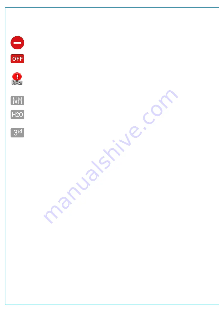
The following icons can be displayed in the I/O patching screen:
This symbol will be displayed if you have been denied access to the port via H2O by the network
administrator.
Whenever a port goes offline this icon is displayed.
Whenever a box or port is set to a different sampling frequency to the console.
If a port has been patched to/from by another Hydra2 user this icon is displayed.
If a port has been patched to/from via H2O this icon will be displayed.
If a port has been patched via a 3rd party controller this icon will be displayed.
Within the I/O patching screen, sources and destinations have separate settings, which are accessible from the left
and right of the control screen footer. The available settings vary depending on which port type is in view:
Channel Settings
If channel inputs are in view, the user can globally switch between viewing input 1 or input 2.
Layer View
When viewing fader specific paths, such as channel inputs or fader inserts, layer view options will be available.
Select layers A or B to view only faders on that layer.
Surface Interaction
When viewing fader specific paths, such as channel inputs or fader inserts, surface interaction options are available.
Checking the
FADER SELECTION FOLLOWS FADER ACCESS
check box brings the currently accessed fader directly
into view within the I/O patching screen at all times.
Connected Destination
The user can view connected destinations from sources and view connected sources from destinations. Both are
displayed within the centre columns with this option selected.
Information Display
When viewing Hydra patchbays or I/O boxes, the information display split-selection button is available to choose
between viewing path descriptions or connected source/destinations within the two centre columns of the screen.
Summary of Contents for BRIO 36
Page 1: ...calrec com Audio Production System with Optional Networking BRIO 36 USER MANUAL V1 1...
Page 12: ...12 BRIO 36 Audio Production System with Optional Networking...
Page 13: ...calrec com BRIO 36 PRODUCT INFORMATION...
Page 20: ...20 BRIO 36 Audio Production System with Optional Networking...
Page 21: ...calrec com BRIO 36 SYSTEM OVERVIEW...
Page 29: ...29 FIGURE 1 BRIO 36 USER INTERFACE DISPLAY...
Page 43: ...calrec com BRIO 36 SETTING UP...
Page 47: ...47 FIGURE 1 SYNCHRONISATION OPTIONS...
Page 67: ...calrec com BRIO 36 GETTING SIGNALS IN AND OUT...
Page 93: ...93 FIGURE 1 THE DIRECT OUTPUT SCREEN...
Page 100: ...100 BRIO 36 Audio Production System with Optional Networking...
Page 101: ...calrec com BRIO 36 PROCESSING...
Page 146: ...146 BRIO 36 Audio Production System with Optional Networking...
Page 147: ...calrec com BRIO 36 MONITORING...
Page 149: ...149 FIGURE 3 EXAMPLE LOUDSPEAKERS SETUP...
Page 155: ...calrec com BRIO 36 METERING...
Page 163: ...calrec com BRIO 36 COMMUNICATIONS...
Page 172: ...172 BRIO 36 Audio Production System with Optional Networking...
Page 173: ...calrec com BRIO 36 ROUTING...
Page 175: ...175 FIGURE 1 CONFIGURING BUSES AND OUTPUTS...
Page 182: ...182 BRIO 36 Audio Production System with Optional Networking...
Page 183: ...calrec com BRIO 36 EXTERNAL INTERFACING...
Page 193: ...calrec com BRIO 36 CONSOLE FACILITIES...
Page 198: ...198 BRIO 36 Audio Production System with Optional Networking...
Page 199: ...calrec com BRIO 36 TERMINOLOGY...
Page 207: ...calrec com BRIO 36 FEATURES BY SOFTWARE VERSION...


