Audio Production System with Optional Networking
Expander/Gate/Ducker
An expander acts in the opposite way to a compressor: When a signal exceeds the expander threshold it is passed
through unchanged, and when it falls below the threshold it is reduced, effectively increasing the dynamic range of the
signal and reducing unwanted audio content.
A gate is effectively an extreme version of an expander, with a very high ratio, resulting in the gain of the input signal being
significantly reduced almost immediately as it falls below the threshold. Gates are often used to minimise unwanted audio
content.
A ducker is used to reduce the level of a signal by the presence of another signal or side chain source. A typical use
of this effect in a daily radio production routine is for creating a voice-over: a foreign language original sound is dubbed
(and ducked) by a professional speaker reading the translation. Ducking becomes active as soon as the translation starts.
Calrec’s expander/gate/ducker processing has 6dB of built-in hysteresis to avoid unwanted ‘chatter’ (constant on/off
switching) resulting from an input signal residing on or around the threshold.
Global Module Controls
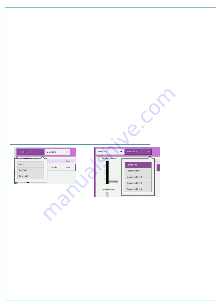
When looking at a dynamics module, any control situated within the screen header affects the whole module as shown in
Figure 3. This includes the following:
•
Each Dynamics module can be inserted either pre EQ, pre fader or post fader. Tap the dynamics position button in
the screen header and select an option.
•
By default, dynamics modules operate as standalone units. The second button in the screen header allows the
module to be put into one of four Dynamics Links.
FIGURE 3 -
GLOBAL DYNAMICS CONTROLS FOR POSITION AND DYNAMICS LINKS
Dynamics Links
Dynamics Links allow multiple audio feeds to have the same dynamics processing applied. When multiple paths’
dynamics modules are set to be part of a Dynamics Link, the amount of gain reduction applied across the link will always
equal that for the signal which is being affected the most. For example, within a Dynamics Link, if one path’s signal is
causing 5 dB of gain reduction and another is causing a reduction of 10 dB, all signals within the Dynamics Link will have
a gain reduction of 10 dB applied. When expander/gate units are used within a Dynamics Link and one feed within the
link reaches the threshold level to open the expander/gate, all expander/gates within the link open regardless of the audio
levels of their feeds.
Compressor/Limiter Controls
•
Threshold: The level (dBFS) at which the signal will begin to have its gain reduced.
•
Ratio: Controls gain reduction once a signal has exceeded the threshold, for example, if the ratio is set at 2:1 and
the signal exceeds the threshold by 4 dBFS, the gain will be reduced so it exceeds the threshold by only 2 dBFS.
When set to 50:1, the compressor is acting as a limiter.
•
Attack: Time taken to reduce the gain to reach the new compressed level. Short attack times enable the compressor
to catch transients in the audio feed, whereas increasing the attack time will focus the compressor on more long term
level issues, such as level differences across various sections of a program.
Summary of Contents for BRIO 36
Page 1: ...calrec com Audio Production System with Optional Networking BRIO 36 USER MANUAL V1 1...
Page 12: ...12 BRIO 36 Audio Production System with Optional Networking...
Page 13: ...calrec com BRIO 36 PRODUCT INFORMATION...
Page 20: ...20 BRIO 36 Audio Production System with Optional Networking...
Page 21: ...calrec com BRIO 36 SYSTEM OVERVIEW...
Page 29: ...29 FIGURE 1 BRIO 36 USER INTERFACE DISPLAY...
Page 43: ...calrec com BRIO 36 SETTING UP...
Page 47: ...47 FIGURE 1 SYNCHRONISATION OPTIONS...
Page 67: ...calrec com BRIO 36 GETTING SIGNALS IN AND OUT...
Page 93: ...93 FIGURE 1 THE DIRECT OUTPUT SCREEN...
Page 100: ...100 BRIO 36 Audio Production System with Optional Networking...
Page 101: ...calrec com BRIO 36 PROCESSING...
Page 146: ...146 BRIO 36 Audio Production System with Optional Networking...
Page 147: ...calrec com BRIO 36 MONITORING...
Page 149: ...149 FIGURE 3 EXAMPLE LOUDSPEAKERS SETUP...
Page 155: ...calrec com BRIO 36 METERING...
Page 163: ...calrec com BRIO 36 COMMUNICATIONS...
Page 172: ...172 BRIO 36 Audio Production System with Optional Networking...
Page 173: ...calrec com BRIO 36 ROUTING...
Page 175: ...175 FIGURE 1 CONFIGURING BUSES AND OUTPUTS...
Page 182: ...182 BRIO 36 Audio Production System with Optional Networking...
Page 183: ...calrec com BRIO 36 EXTERNAL INTERFACING...
Page 193: ...calrec com BRIO 36 CONSOLE FACILITIES...
Page 198: ...198 BRIO 36 Audio Production System with Optional Networking...
Page 199: ...calrec com BRIO 36 TERMINOLOGY...
Page 207: ...calrec com BRIO 36 FEATURES BY SOFTWARE VERSION...


