background image

Setting Up the Cabling Infrastructure 

Note

Changing a cell to Damaged status will not automatically disconnect the cable from this 

port; i.e., you will have a connection to a damaged pair/strand.  

You cannot change the status from Available to Used. To accomplish that, you must make or 
break the connection in the 

Source

 and 

Destination

 tabs. 

Backbone Cross-Connects 

The Cross-Connects tab shows status for Source and Destination cross-connects. This form can 
be edited.  Note that cross-connects are only applicable at the backbone ends that are connected 
to termination hardware. 

1.


To make a cross-connect, click the 

Connection Type

 for the cable pair to which you 

wish to cross-connect. A drop-down list appears with Available, Horizontal Link, 
Backbone Cable, and Asset.   

2.


Choose the type of cable (or asset) to which you want to cross-connect. In order to cross-
connect to cable, that cable must be connected to termination hardware. 

3.


Click in the 

Connection ID

 cell and select the ID of the item to which you are cross-

connecting.  Only items connected to termination hardware in that backbone’s space are 
available. 

4.


Click the cell in the 

Pair #

 column. The 

Select Items

 window appears with a list of the 

available pairs/strands for the selected item. Select the pairs/strands to which you are 
cross-connecting.  

5.


The 

Termination Hardware

 and 

Port/Pos

 columns will automatically populate with the 

termination hardware to which the other end of the cross-connected cable is attached. 

Identifying Backbone Pathways Used  

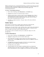
The Pathways Used tab identifies the Pathways in which the backbone is located. When adding 
Pathways, add them in order from Source to Destination.  

To add pathways used: 

1.


Highlight the 

Pathways Used 

tab.  

2.


Click the 

Add 

button in the Detail area. The Location window appears. Select the first 

Pathway this backbone is in. Click 

Accept

.  

3.


Segment, Pathway ID, Pathway Type, and Source are populated on the table.  

4.


Click 

Save 

to save the new information. The Segment column identifies the order in 

which the backbone uses each of the pathways.  

Connecting a Backbone to a Grounding Conductor 

See 

Adding a Ground

75 

Summary of Contents for NetDoc

Page 1: ......

Page 2: ...ur IIS Server 7 Creating the SQL Server Database 9 Configuring SQL Server Security optional 13 Configuring IIS to Display NetDoc on an Intranet 16 To configure IIS for Windows Server 2000 16 To config...

Page 3: ...copy to Excel 39 To Clipboard Button 40 To copy to the clipboard 40 Circuit Trace Tool 40 About the Circuit Trace Tool 40 Accessing the Circuit Trace Tool 40 Viewing Circuit Information 41 Show Hide...

Page 4: ...58 To add a Floor 59 To remove a Floor 59 Indoor Spaces 59 To add an Indoor Space 59 Telecommunication Spaces 60 To add a Telecommunication Space 60 Outdoor Spaces 61 To add an Outdoor Space 61 To re...

Page 5: ...ntifying Horizontal Link Pathways Used 71 Editing the Key Sheet 71 Connecting a Horizontal Link to a Grounding Conductor 71 Splices 71 Adding Splices 71 Splice Types User Defined 72 Connecting a Backb...

Page 6: ...ltering and Grouping Reports 82 Selecting Data for a Report 82 Grouping Data on a Report 83 Sorting a Report 83 Report Detail 83 Header Color 83 The Print Details Button 83 Available Reports 83 An add...

Page 7: ...you would naturally read them Click on the category to list its individual topics Click a topic to display it Index Displays an organized list of related topics Browse the list or type a keyword and...

Page 8: ...f this document Brady assumes no liability to any party for any loss or damage caused by errors or omissions or by statements resulting from negligence accident or any other cause Brady further assume...

Page 9: ...Preface Technical Support Contact Information United States and Canada Phone 1 800 643 8766 M F 6 30 a m 6 30 p m Central Time FAX 1 800 358 6767 Email tech_support bradycorp com 3...

Page 10: ...ted into LabelMark software to assist you in easily labeling your entire infrastructure Brady s documentation solutions labeling solutions and an assortment of printers will increase productivity redu...

Page 11: ...ble printer Requirements Windows 2000 Windows XP Home or Windows XP Professional Internet Explorer 6 0 Server Requirements Hardware Software Minimum Requirements 750 MHz Processor 512 MB Ram 30 GB dis...

Page 12: ...ly with IIS For that reason we strongly suggest you install or reinstall NET Framework before configuring anything NET Framework can be downloaded from www microsoft com An individual with administrat...

Page 13: ...This part of the installation process applies to both MS Windows Server 2000 and 2003 To install NetDoc on an IIS server 1 Insert the NetDoc CD into the CD ROM drive The install screen appears If the...

Page 14: ...ULA screen appears click Yes to accept it If you decline the agreement the software will not install 5 In the Customer Information screen enter your User Name Organization and Serial Number serial num...

Page 15: ...nstall Setup will begin copying files 9 When the Setup Complete screen appears click Finish The setup is complete Creating the SQL Server Database This section steps you through the process of creatin...

Page 16: ...NetDoc User Guide 5 The Database Properties window appears On the General tab enter a name for the database in the Name field Make a note of the name as you will need it later 6 Click OK 10...

Page 17: ...alling NetDoc 7 Expand the database tree by clicking the plus symbols and select the database you just created 8 Click the Tools menu and select SQL Query Analyzer 9 Click the File menu and select Ope...

Page 18: ...NetDoc sql file and then click Open 12 Click Execute Query 13 Confirm that Query batch completed is shown at the bottom of the window If you receive an error message please consult Microsoft s SQL 20...

Page 19: ...erform all SQL configurations for security purposes Note This part of the installation process applies to both MS Windows Server 2000 and 2003 To add the database user in SQL Server 1 From the Start m...

Page 20: ...gin Properties New Login dialog box appears enter your new login name in the Name field 6 Click to select SQL Server Authentication 7 Enter a password Make a note of the name and password you entered...

Page 21: ...Installing NetDoc 9 In the Database User Properties dialog box click the down arrow next to Login name and select your newly added name 10 Click the checkbox for db_owner 11 Click OK 15...

Page 22: ...o connect to the database see Connecting to the SQL Server Database IMPORTANT NOTE For this phase of the installation process the steps you follow depend on whether you are using MS Windows Server 200...

Page 23: ...Installing NetDoc 4 In the NetDoc Properties window click the Security tab 5 Click the Add button 17...

Page 24: ...k the checkbox for Write in the Allow column of the Permissions area Recommendation Deleting an attachment in NetDoc does not remove the attachment from the hard disk Granting the ASP NET user Modify...

Page 25: ...me then expand the Default Web Site option Right click NetDoc and select Properties 4 In the NetDoc Properties window ensure that Application Protection is set to Low 5 Click the Directory Security Ta...

Page 26: ...select IIS_WPG user from the list If you cannot locate IIS_WPG user on the list 1 click the Advanced tab 2 use the Find Now function to locate it 3 select it and 4 click OK When the IIS_WPG user appea...

Page 27: ...as you will need it later 3 Expand your server name then expand the Default Web Site option Right click NetDoc and select Properties 4 In the NetDoc Properties window ensure that Application Protecti...

Page 28: ...base and User names see Add Database User to SQL and Password This is the information you noted earlier when you created the SQL server database and added the database user to the server 6 Click Conne...

Page 29: ...ng editing passwords and password change requirements Standard Read Only checkbox not checked on the Contact screen User may view and edit component information in existing infrastructures The user ma...

Page 30: ...e shipped with the software The file can be found in the root of the directory where it was installed Note This part of the installation process applies to both MS Windows Server 2000 and 2003 To acce...

Page 31: ...create users but they cannot assign user names or passwords to allow those users access to NetDoc A contact created by a Non Admin must have a user name and password subsequently assigned by an Admin...

Page 32: ...The install server screen should appear If the install does not start automatically select Run from the Start menu type D setup exe and skip to step 3 Click Install NetDoc 3 When the InstallShield We...

Page 33: ...The NetDoc Main Page When you login to NetDoc the first screen will be the Main Page The Main Page is the entry page to access all of NetDoc s features Every additional page you view in NetDoc has a...

Page 34: ...documenting your network components Help Opens the online help feature About Provides the NetDoc version number REPORTS menu Report Creator Opens a pop up window from which you can generate a variety...

Page 35: ...records with the same default information at the same time SETUP menu Companies Opens a pop up window where you can add edit or delete Companies in your documentation Infrastructure Opens a pop up wi...

Page 36: ...tree Click the Company icon or anywhere on the Company name and the List View and Detail View areas are populated with information filtered according to the selected category For example If you click...

Page 37: ...ubicle Hallway Warehouse Kitchen or Office is considered to be an Indoor Space Faceplate While many elements of cabling infrastructure can be added at any time after the geographical infrastructure is...

Page 38: ...ward indicating the records are sorted in descending order The first column of the List View pane consists of a clickable button that allows you to display the detailed view for that component in a po...

Page 39: ...HW Info and Port Pos Details The tabs shown in the Detail area will change according to the category selected in the drop down field and sometimes will even change in the same category but with diffe...

Page 40: ...tly your documentation network drawings photos and all other needed files are stored in one easy to reach location To add an Attachment 1 In the Attachment area click Add 2 In the Attachment pop up wi...

Page 41: ...type your notes into the given Notes box 2 Click Save in order for your notes to be saved properly After the Save button has been clicked your entered note will move below the Notes box The newly crea...

Page 42: ...ll components once deletion has been completed Revision Log At every level of the infrastructure each component s Detail View lists the user name of the individual who added the component to the struc...

Page 43: ...er report so you simply restore the screen to create the report without having to go back to the home page to gain access to this tool This NetDoc feature saves time and makes the application easier t...

Page 44: ...m section features available on all NetDoc tables Click the box in the first column by any item to open the Detail View for that item and make any changes Quick Set Quick Insert Buttons Throughout Net...

Page 45: ...s To use the Copy function 1 In the List View select the component you wish to copy 2 Click the Copy button 3 A new record row will be added to the List View table and the data you copied will be disp...

Page 46: ...ace Tool About the Circuit Trace Tool NetDoc s Circuit Trace Tool allows you to view in both text and graphic format all the components of an individual circuit Circuit tracing is especially helpful i...

Page 47: ...the Navigation Tree showing its location hardware only and links to view all the ports or pairs strands connected to that component both taken and available Lines linking the images indicate how the c...

Page 48: ...Circuit Trace window you can open a pop up window displaying the Detail View information for any component shown in this window To view a component s Details View information 1 Click the component s I...

Page 49: ...mbered steps displayed 1 In the Filter by Object drop down field select what objects your labels will be created for In the Type drop down field select the type of objects to create labels for You can...

Page 50: ...y converting your test results into a CSV file NetDoc stores all information in its appropriate location as designated by the importing user The importing of tester results is performed completely thr...

Page 51: ...cted the file and the link appears in the Step 2 field click the Open button Note If your test results have leading and trailing quotes they can be removed by selecting the check box below the Step 2...

Page 52: ...ata will be in the format exported by your specific tester machine See also Viewing Tester Data Viewing Test Data To view test data 1 Click the Launch Application link on the NetDoc Main Page 2 From t...

Page 53: ...use The link for User Defined Fields resides within the Tools section of the NetDoc Main Page menu Upon clicking this the Field Editor pop up window appears By using the drop down field you can selec...

Page 54: ...in the columns of that row 4 In the Description fields enter the desired field name 5 Click Save The custom fields you add will appear either as additional fields displayed on the Detail View for a c...

Page 55: ...ge fields and then clicking Search Export the data to an Excel spreadsheet by clicking the To Excel button Change the sort order from ascending to descending or vice versa of any of the columns For ex...

Page 56: ...rtant areas of your infrastructure Using NetDoc to document these areas is recommended but hiding these areas and not using them is up to the user s discretion Most importantly these sections can be h...

Page 57: ...ing needed by creating small blocks of components at a time the user can go through the application quickly to complete the needed documentation See the warning below for additional reasons for these...

Page 58: ...ve not yet been added to the database and can be discarded if necessary If the information is correct click the Save button The Navigator Tree will be updated with the infrastructure components you cr...

Page 59: ...you see all the items listed out before you save them in the database The naming numbering feature of these wizards all function in the same way Other information entered into the wizard is specific...

Page 60: ...seconds the application has no global delete capability Given this deletion still must be completed by going to each specific item and deleting the items one by one The above recommendations for using...

Page 61: ...by clicking the Add button or you can add them all at once by clicking the Wizard button Note Although you aren t required to set up your entire geographical infrastructure you must create the basics...

Page 62: ...NetDoc User Guide items exist underneath it a NetDoc warning box pops up The company cannot be deleted until subordinate items are removed 56...

Page 63: ...he window Repeat for each campus within your company 3 Attachments and Notes are available as needed In the Company Info window you may insert a Company drawing by clicking the Add link in the Attachm...

Page 64: ...Save when you are finished 6 A plus sign will appear next to the campus icon indicating that there is infrastructure information at the next level down Click plus changing it to a minus to expand and...

Page 65: ...he floor name To remove a Floor 1 On the NetDoc Main Page select Infrastructure on the SETUP menu 2 Highlight the building name or icon where the floor is housed 3 Click the floor you wish to remove a...

Page 66: ...s name will be removed from the Navigator Tree Telecommunication Spaces NetDoc categorizes floor space as either a Telecommunication Space or a Work Area A Telecommunication Space is where terminatio...

Page 67: ...f the infrastructure NetDoc lets you designate building space and outdoor space Building space can include cubicles rooms termination rooms closets and any space defined in your facility You can also...

Page 68: ...wish to add a faceplate 3 The Space Info screen appears with the space name Click the Add button and add the name of the faceplate 4 Click Save to save the faceplate information The new faceplate will...

Page 69: ...ars with the faceplate s name and any existing ports listed in a table Click the Add button 4 Enter the name of the port to the new row at the bottom of the table 5 Click Save to save the port informa...

Page 70: ...sides must be set up Termination Hardware should be placed in an appropriate Telecommunication Space a Consolidation Point Entrance Room Handhole Manhole Termination Closet Closet Point or Utility Pol...

Page 71: ...exiting the window Start and End Port Position Start and End Port Position lists the number of physical connections that exist in a specific piece of termination hardware For Patch Panels ports are d...

Page 72: ...f your company should be set up in the Navigator Tree Assets can then be associated with the physical spaces in which they reside See Setting Up the Geographical Infrastructure Setting Up Asset Types...

Page 73: ...dd a Workstation Asset 1 Click on the Work Area in the Navigator Tree where you want to add an asset 2 Click on the Assets section in the List View pane drop down field 3 Click the Add button Financia...

Page 74: ...set up if the HL is cabled but it is not yet determined whether it will carry voice or data 5 Fill in the HL ID Pressing the Tab key after inputting the HL ID field will populate the Cable ID field wi...

Page 75: ...ontal Link You may however select users associated with this link 1 Click the yellow ellipsis button next to the Contact field 2 The Select Contact window pops up with all users associated with the sp...

Page 76: ...window appears with the voice backbone assets listed To find the correct asset easily you can sort any column by clicking in the column heading Select the asset the voice horizontal link will connect...

Page 77: ...play The form on the lower part of the tab contains information pertaining to the actual connection To edit the key sheet 1 Click the Add button in the Detail area to enter Line Extension and COS 2 Yo...

Page 78: ...e Connecting a Backbone Cable to a Splice This must be done from the Backbone area See Backbones Once you have spliced a backbone cable you can view all backbones connected to a splice in the Connecte...

Page 79: ...l area select the yellow ellipsis button to the right of the Backbone Type field 2 Click the Add button 3 In the pop up Customizable Fields window enter the Backbone Type 4 The Descriptions columns al...

Page 80: ...ow 2 Select the Destination from the tree Building Floor and Space are populated unless you are connecting from an outdoor space such as a Utility Pole In that case only Space is populated 3 Click Acc...

Page 81: ...ell and select the ID of the item to which you are cross connecting Only items connected to termination hardware in that backbone s space are available 4 Click the cell in the Pair column The Select I...

Page 82: ...the ID in the Busbar ID field 6 Select the busbar type from the drop down list in the Busbar Type field 7 Click Save Note TMGB Telecommunications Main Ground Busbar is the main busbar that goes direct...

Page 83: ...ackbone ID and click OK The Backbone ID and Type fields are populated Busbar Busbar ID and Type fields appear Click the button next to the Busbar ID field When the Select Item window appears select th...

Page 84: ...space highlighted in the Navigator Tree 4 In the Info tab fill in the Firestop ID Manufacturer and UL fields 5 In the Destination box click the Set Location button 6 When the Location window appears...

Page 85: ...to a Firestop Firestops must first be set up in the Firestops tab To connect a pathway to a firestop 1 Click the Connected Firestops tab on the Pathways Detail View for the selected pathway 2 Click th...

Page 86: ...ber as well as User Name Passwords permission levels and User Type 4 If you are entering the Contact information from a space other than the user s workspace click on the Set Location button in the Lo...

Page 87: ...e tab One user may be assigned to several horizontal links To connect a user to a horizontal link 1 In the Connected HLs tab click the Add button 2 When the Horizontal Link window appears click the HL...

Page 88: ...eport window There are four sections in the report window These allow you to customize the information that appears in your report and how it is displayed The four sections are Selection Criteria Grou...

Page 89: ...check details specific to that report for inclusion For example in the Asset Details report you may check Show Accounting Information and or Show Attributes In the Space report you may select Show Fa...

Page 90: ...hway Source or Pathway Destination The information can be grouped by Pathway Type Space Report can be filtered by Department Name Connection Rating or Location TR Report can be filtered by Backbone Ty...

Page 91: ...you add your existing data to the worksheet 2 Next you use the tool s Check Data macro to verify the data s integrity and identify data that cannot be authenticated 3 When you activate the Import Dat...

Page 92: ...worksheet tab for the type of data you want to import Assets Termination Hardware Backbone Cables Horizontal Links or Users 2 Use Excel s import function to add data from other files or copy and paste...

Page 93: ...invalid or uses the wrong date format the data does not match a option e g a Horizontal Link type may only be Data Voice or Unused if that field in the spreadsheet contains another value or if the inf...

Page 94: ...acked See Adding a Horizontal Link and Adding a Backbone Firestops You can keep track of the location and type of every firestop in your infrastructure When new cabling entrances through firewalls are...

Page 95: ...are output to HTML When generated they will appear as you have specified them in your web browser and can be printed in color See Reports Reporting capabilities include the ability to print details o...

Reviews: