Technical data • Fully assembled device
58
Automation PC 810 with GM45 CPU board user's manual V1.28
2.6.13 Status LEDs
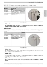
Status LEDs are integrated in the system unit behind the orange front cover.
Status LEDs
LED
Color
Status
Description
Green
On
Supply voltage OK
Red
On
System in standby mode (S5: Soft-off mode, S4:
Hibernation mode or S3: Suspend-to-RAM)
Power
Orange
1)
On
Supply voltage not OK, system operating on bat-
tery power
HDD
Yellow
On
Indicates IDE drive access (CF, HDD, CD, etc.)
On
Indicates an active SDL connection on the moni-
tor/panel connector
Link1
Yellow
Blinking
Indicates that an active SDL connection has been
interrupted by a loss of power to the display unit
On
Indicates an active SDL connection on the AP
Link.
Link2
Yellow
Blinking
Indicates that an active SDL connection on the
AP Link has been interrupted by a loss of power
to the display unit
Table 29: Status LEDs - Data
1)
Only lit when an add-on UPS module is installed.
The light for the Status LEDs is fed to the front cover via fiber optic lines.
Figure 18: Status LEDs on the front
2.6.14 CMOS profile switch
CMOS profile switch
Different BIOS default value profiles can be specified using the 16-position CMOS pro-
file switch.
Switch position
Description
0
Profile 0: Default profile reserved.
1
Profile 1: Optimized for system units
5PC810.SX01-00, 5PC810.SX02-00 and
5PC810.SX03-00
2
Profile 2: Optimized for 5PC810.SX05-00 system unit
3
Profile 3: Optimized for system units 5PC820.SX01-00
and 5PC820.SX01-01
4
Profile 4: Reserved
5
Profile 5: Optimized for system units 5PC820.1505-00
and 5PC820.1906-00
0 - F Hex
Table 30: CMOS profile switch
Information:
The switch position that is set upon delivery represents the optimum BIOS default values for this
system and should therefore not be changed.
The position of the CMOS profile switch is displayed in the BIOS setup pages and in the B&R ADI Control Center,
among other places.

