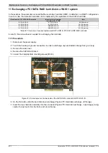
Maintenance / Service • Mounting the side cover
398
Automation PC 810 with GM45 CPU board user's manual V1.28
9.3 APC810 with 5 card slot
1. Disconnect the power supply to the Automation PC 810.
2. Touch the housing or ground connection in order to discharge any electrostatic charge from your body.
3. Open the orange front cover. The Combi-Torx screws (T10) behind the cover that are marked in the image
must be removed.
4. After the screws have been removed, the side cover can be removed by sliding it toward the front.
Remove 6 screws
Figure 271: Mounting the side cover - APC810 with 5 card slot

