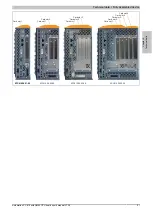
Technical data • Fully assembled device
Chapter 2
Technical data
Automation PC 810 with GM45 CPU board user's manual V1.28
45
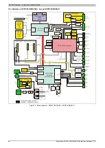
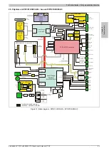
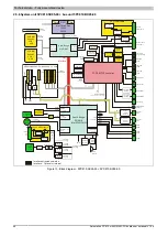
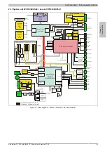
2.5.7 System unit 5PC810.SX05-00 + bus unit 5PC810.BX05-01
UPS
UPS
PCIe bus
PCIe (Lane 0-5)
PCIe (4)
PCIe (5)
SATA 1
DC/DC
Switching
+12 volts
SM bus
Clock generator
SM bus
Memory
Controller
Graphics
Controller
Hardware
Monitor
CPU temperature
Temperature
Sensor I/O
Temperature
Sensor power supply
RAM 128 kB
Serial Flash
Serial EEPROM
Factory settings
Ethernet
Controller
Intel 82573L
Monitor / Panel
SDL1 / DVI-I
Power LED
red/green/orange
HDD LED
Yellow
Link1 LED
Yellow
Link2 LED
Yellow
Power button
Ethernet
ETH2
Ethernet
ETH1
USB1
USB2
RS232 COM1
RS232 COM2
Security key
Real-time clock
RTC
USB
Controller
Optional
Slide-in compact
SATA hard disk
Battery
950 mAh
V battery
Line driver
RS232
Line driver
RS232
SM bus
BIOS
Flash
Buffering 10 ms
Voltage
supply
3-pin
DC/DC
Isolated
DC/DC
Switching
DC/DC
Switching
+5 volts
+3.3 volts
+15.6 volts
Reset button
Optional
Fan 1
Optional
Fan 2
Optional
Fan 3
IF option CAN
or RS485
Analog RGB
SDL IF
SDVO B
DMI
Interface
SM bus
SATA 0
TMDS
Sil 1362A
Battery
Unit
6-pin
Position controller
Temperature sensors
Controller
Add-on UPS module
512 kB SRAM
Battery-buffered
Core
Core
CMOS Profile
switches
USB3
USB4
USB5
Piezzo
Buzzer
FPGA MTCX controller
USB0
USB1
USB2
USB3
USB4
USB5
USB7
USB6
V battery
System bus
+5 volts
SM bus
Voltage monitoring
Voltage monitoring
I²C
PCI bus
Interface directed outwards
Interface - Optional or internal
PC
Ie
X
1
Sl
ot
5
PC
Ie
X
1
Sl
ot
4
PC
Ie
X
1
Sl
ot
3
5PC810.BX05-01 - 5 slot bus 2 PCI / 3 PCIe
SATA
Contr.
USB
HUB
PC
Ie
(0
)
PC
Ie
(3
)
PC
Ie
(2
)
PC
Ie
(1
)
32
-b
it
PC
I b
us
s
lo
t 1
32
-b
it
PC
I b
us
s
lo
t 2
SA
TA
1
I²C
Sl
id
e-
in
s
lo
t 1
Sl
id
e-
in
s
lo
t 2
I²C
USB5
SA
TA
2
SDVO C
AP Link
SDL2 / DVI-D
AP Link module
LVDS
Sil 1362A
Altera
FPGA
USB7
SATA to
PATA
SATA 3
North Bridge
Intel GM45
South Bridge
ICH9M-E
Intel 82801GHM
SATA 1
Controller
CPU
Intel Core2 Duo
T9400
P8400
CompactFlash
Slot 1
SATA 0
Controller
SO-DIMM
Module 2
2 GB -
4 GB
SO-DIMM
Module 1
2 GB -
4 GB
HDA sound
Controller
Ethernet
Controller
Intel 82567
Figure 14: Block diagram - 5PC810.SX05-00 + 5PC810.BX05-01


