Maintenance / Service • Installing the ready relay /2 in the add-on UPS slot
Chapter 7
Maintenance / Service
Automation PC 810 with GM45 CPU board user's manual V1.28
403
13 Installing the ready relay /2 in the add-on UPS slot
13.1 Procedure
1. Remove side cover (see section 9 "Mounting the side cover" on page 397).
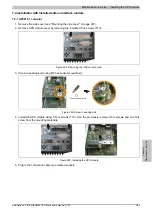
2. Remove UPS module cover or mounted UPS by loosening the 2 marked Torx screws (T10).
Figure 278: Removing the UPS module cover
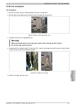
3. Attach spacing bolt and spacing ring (if not already mounted from the UPS) on the main board (using
size 5 hex screwdriver). The spacing bolt with a length of 14 mm must be used for APC810 system units
5PC810.SX01-00, 5PC810.SX02-00 and 5PC810.SX03-00. The spacing bolt with a length of 16 must be
used for the system unit 5PC810.SX05-00.
Spacer bolt
+ Spacer ring
Figure 279: Screw in spacing bolt and spacing ring
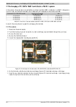
4. Ready relay with 2 Torx screws (T6) and the mounting bracket on the housing and 1 Torx screw (T6) on the
main board (spacing bolt).
Figure 280: Installing the ready relay
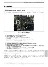
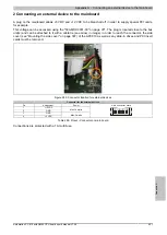
5. Plugging in the connection cable
Information:
When connecting the internal supply voltage cable, make sure that the connector locking mech-
anism is engaged.

