Maintenance / Service • AP Link installation
Chapter 7
Maintenance / Service
Automation PC 810 with GM45 CPU board user's manual V1.28
399
10 AP Link installation
10.1 Procedure
1. Remove the side cover (see "Mounting the side cover" on page 397).
2. Remove AP Link module cover by removing the 2 marked Torx screws (T10).
Figure 272: Remove AP Link module cover
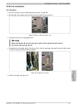
3. Insert the AP Link card in appropriate slot.
Warning!
When inserting the AP Link card, be sure to push it all the way into the AP Link slot.
Do not force the card into the slot.
4. Install the AP Link module using 3 Torx screws (T10). Use the previously removed Torx screws and an addi-
tional Torx screw from the mounting materials.
Figure 273: Install AP Link module
5. Attach cover plate and side cover.

