Software • BIOS options
254
Automation PC 810 with GM45 CPU board user's manual V1.28
PCI-EX Port 1
B0:D28:F1
PCI-EX Port 0
B0:D28:F0
PCI-EX Port 2
B0:D28:F2
PCI-EX Port 3
B0:D31:F3
Intel 82567
B30:D25:F0
(PCI-EX Slot 5)
CPU module
VGA
B0:D2:F0, B0:D2:F1
HDA
B0:D27:F0
USB UHCI-3
B0:D26:F0
USB UHCI-0
B0:D29:F0
SM bus
B0:D31:F3
USB EHCI-0
B0:D29:F7
USB EHCI-1
B0:D26:F7
Native IDE
B0:D31:F5
(SATA 0 + 1)
Intel 82573L
B2:D0:F0
(PCI-EX Slot 4)
Mainboard
Sil 3531
B2:D0:F0
(PCI-EX Slot 0)
PIRQ A
APIC IRQ 16
PIRQ B
APIC IRQ 17
PIRQ C
APIC IRQ 18
PIRQ D
APIC IRQ 19
PIRQ F
APIC IRQ 21
PIRQ G
APIC IRQ 22
PIRQ H
APIC IRQ 23
PIRQ E
APIC IRQ 20
USB UHCI-2
B0:D29:F2
USB UHCI-1
B0:D29:F1
PCI Bus
A
A
A
A
B
B
B
B
C
C
C
C
D
D
D
D
Sil 3531
B2:D0:F0
(PCI-EX Slot 0)
PCI 1 PCI 2 PCI 3
PCI 4
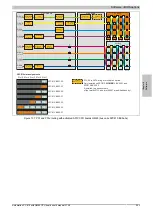
APC810 slot assignments
5PC810.BX05-02
Slot 1
Slot 2
Slot 3
Slot 4
Slot 5
PCI 1
PCI-EX to SATA bridge for slide-in 2 option.
Only installed on 5PC810.BX05-00,
5PC810.BX05-01 and
5PC810.BX05-02.
If installed, the bus numbers
of the Intel 82573L and Intel 82567 are shifted back by 1.
PCI 2
PCI 3
PCI 4
PCI 5
A
B
C
D
PCI 5
1) The PCI4 and PCI5 slots are located behind an additional
PCI to PCI bridge. (see block diagram for 5PC810.BX05-02 bus)
1)
1)
Figure 138: PCI and PCIe routing with activated APIC CPU boards GM45 (bus unit 5PC810.BX05-02)


