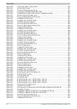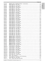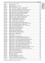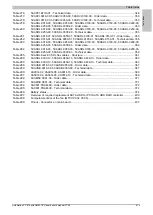
Appendix A • Maintenance Controller Extended (MTCX)
Appendix A
Automation PC 810 with GM45 CPU board user's manual V1.28
405
Appendix A
1 Maintenance Controller Extended (MTCX)
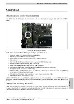
The MTCX controller (FPGA processor) is located on the main board (part of every system unit) of the APC810
device.
MTCX
Figure 282: MTCX controller location
The MTCX is responsible for the following monitoring and control functions:
•
Power on (power OK sequencing) and power fail logic
•
Watchdog handling (NMI and reset handling)
•
Temperature monitoring (I/O area, power supply, slide-in drive 1/2)
•
Fan control
•
Key and LED handling/coordination (matrix keyboard on B&R display units)
•
Advanced desktop operation (keys, USB forwarding)
•
Daisy chain display operation (touch screen, USB forwarding)
•
Panel locking mechanism (can be configured using B&R Control Center - ADI driver)
•
Backlight control for a connected B&R display
•
Statistical data recording (Power cycles - records every switch-on, power on and fan hour; every full hour
is counted, i.e. no increase at 50 minutes)
•
SDL data transfer (display, matrix keyboard, touch screen, service data, USB)
•
Status LEDs (Power, HDD, Link 1, Link 2)
Extended MTCX functions are available by upgrading firmware
6)
. The version can be read in BIOS (menu item
"advanced" - baseboard/panel features) or in approved Microsoft Windows operating systems, using B&R Control
Center.
1.1 Temperature monitoring - Fan control
The MTCX constantly monitors the temperature using temperature sensors (see "Temperature sensor locations"
on page 28), which directly determine how the fan is controlled. The RPM depends on the temperature measured.
The limit values depend on the MTCX firmware version being used.
6)
Available in the Downloads section of the B&R website (
).


