IP Office Basic Edition - Quick Mode Installation
Page 76
15-601042 Issue 24i (20 December 2011)
IP Office 8.0
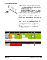
4.10 Starting the System
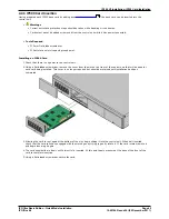
1. With the IP500 V2 control unit shut down or unpowered, insert the Avaya
System SD card into the System SD slot on the rear of the control unit.
·
On newer controls units, the SD card slots are partially covered by a
plastic tab. Partial release the screw holding the tab so that it can be
moved clear of the required card slot.
·
Ensure that you have the correct card.
·
Ensure that the card has the level of software required. If necessary
the card can be upgraded to match the version of IP Office Manager.
2. Apply power to the external expansion modules if any. The power outlet
used must include a switch and in cases where the power cord includes
an earth lead, that outlet must have a protective earth connection.
3. Apply power to the IP500 V2 control unit. The power outlet used must
include a switch and the power outlet must have a protective earth
connection.
4. The control unit will begin loading firmware from the System SD card with
which it will upgrade itself and the components installed in the control
unit.
5. This process takes approximately a minute. The end of this process will
be indicated by LED1 on each base card flashing every 5 seconds. LED9
on each base card fitted with a trunk daughter card will also flash every 5
seconds.
6. The control unit will then begin upgrading the external expansion
modules. This will be indicated by the red center LED on each module
flashing red. The process is completed when the LED changes to steady
green.
7. It should be possible now to use IP Office Manager to access the
configuration of the IP Office.
The LEDs on the rear of the control unit go through the following sequence during a normal start up. Note that the times
are approximately only:
LED
4s
4s
12s
5s
2s
5s
5s
10s
10s
Finished
CPU
Orange
Green
Green
Green
Green
Green
Green
Green
Green
Green
Red
System SD
Orange
Off
Green
Green
Green
Off
Green
Green
Green
Green
Flash
Optional SD
If present.
Orange
Off
Green
Green
Green
Off
Off
Green
Green
Green
On the front of the control unit, LED1 on any IP500 base cards fitted is used as follows. LED9 is also used for any trunk
daughter cards fitted.
LED
30s
30s
Finished
LED1/LED9
Red
Red
Red
Fast Flash
Flash every 5
seconds

