DRV-28 inverter
s Function parameter list
-198-
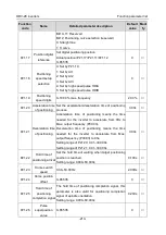
Function
code
Name
Detailed parameter description
Default
value
Modi
fy
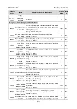
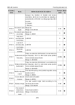
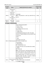
0000–000F
Corresponds to R02, RO1, HDO and Y1 respectively
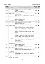
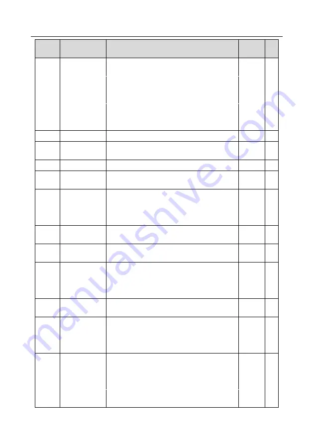
P17.14
Digital
adjustment
variable
Display the regulating variable by UP/DOWN
terminals of the inverter.
Range: 0.00Hz–P00.03
0.00Hz
●
P17.15
Torque reference
value
Relative to percentage of the rated torque of current
motor, display torque reference.
Range: -300.0%–300.0% (rated motor current)
0.0%
●
P17.16
Linear speed 0–65535
0
●
P17.17
Reserved
variables
0–65535
0
●
P17.18
Count value
0–65535
0
●
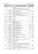
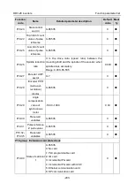
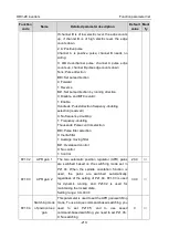
P17.19 AI1 input voltage
Display input signal of AI 1
Range: 0.00–10.00V
0.00V
●
P17.20 AI2 input voltage
Display input signal of AI2
Range: -10.00V–10.00V
0.00V
●
P17.21
HDIA input
frequency
Display input frequency of HDIA
Range: 0.000–50.000kHz
0.000
kHz
●
P17.22
HDIB input
frequency
Display input frequency of HDIB
Range: 0.000–50.000kHz
0.000
kHz
●
P17.23
PID reference
value
Display PID reference value
Range: -100.0–100.0%
0.0%
●
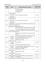
P17.24
PID feedback
value
Display PID feedback value
Range: -100.0–100.0%
0.0%
●
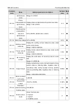
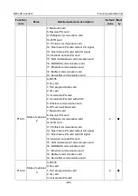
P17.25
Motor power
factor
Display the power factor of current motor.
Range: -1.00–1.00
1.00
●
P17.26
Current running
time
Display current running time of the inverter.
Range: 0–65535min
0m
●
P17.27
Simple PLC and
current step
number of
multi-step speed
Display simple PLC and current step number of
multi-step speed
Range: 0–15
0
●
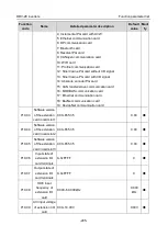
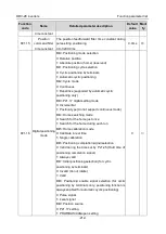
P17.28
Motor ASR
controller output
Display the speed loop ASR controller output value
under vector control mode, relative to the percentage
of rated torque of the motor.
Range: -300.0%–300.0% (rated motor current)
0.0%
●
P17.29
Pole angle of
open-loop
Display initial identification angle of synchronous
motor
0.0
●

