DRV-28 inverter
s Extension cards
-301-
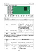
Indicator No.
Definition
Function
LED2
Bluetooth
communication state
indicator
This
indicator
is
on
when
Bluetooth
communication is online and data exchange can
be performed.
It is off when Bluetooth communication is not in
the online state.
LED5
Power indicator
This indicator is on after the control board feeds
power to the Bluetooth card.
SW1
WIFI factory reset
button
It is restored to default values and returned to
the local monitoring mode.
SW2
WIFI hardware reset
button
It is used to reboot the extension card.
The wireless communication card is especially useful for scenarios where you cannot directly use the
keypad to operate the inverter due to the restriction of the installation space. With a mobile phone
APP, you can operate the inverter in a maximum distance of 30 m. You can choose a PCB antenna or
an external sucker antenna. If the inverter is located in an open space and is a molded case machine,
you can use a built-in PCB antenna; and if it is a sheetmetal machine and located in a metal cabinet,
you need to use an external sucker antenna.
When installing a sucker antenna, install a wireless communication card on the inverter first, and then
lead the SMA connector of the sucker antenna into the inverter and screw it to CN2, as shown in the
following figure. Place the antenna base on the chassis and expose the upper part. Try to keep it
unblocked.
The wireless communication card must be used with the Astraada Inverter APP. Scan the QR code of
the inverter nameplate to download it. For details, refer to the wireless communication card manual
provided with the extension card. The main interface is shown as follows.

