DRV-28 inverter
s Function parameter list
-210-
Function
code
Name
Detailed parameter description
Default
value
Modi
fy
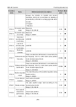
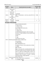
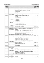
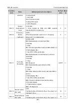
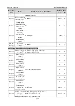
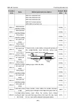
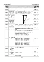
If channel B is of low electric level, the edge counts
up; if channel B is of high electric level, the edge
counts down.
2: A: Positive pulse
Channel A is positive pulse; channel B needs no
wiring
3: A\B dual-channel pulse; channel A pulse edge
counts up, channel B pulse edge counts down
Tens: Pulse direction
Bit0: Set pulse direction
0: Forward
1: Reverse
Bit1: Set pulse direction by running direction
0: Disable, and BIT0 is valid;
1: Enable
Hundreds: Pulse/direction frequency-doubling
selection (reserved)
0: No frequency-doubling
1: Frequency-doubling
Thousands: Pulse control selection
Bit0: Pulse filter selection
0: Inertia filter
1: Average moving filter
Bit1: Overspeed control
0: No control
1: Control
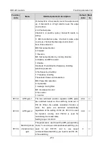
P21.02
APR gain 1
The two automatic position regulator (APR) gains
are switched based on the switching mode set in
P21.04. When the spindle orientation function is
used, the gains are switched automatically,
regardless of the setting of P21.04. P21.03 is used
for dynamic running, and P21.02 is used for
maintaining the locked state.
Setting range: 0.0–400.0
20.0
○
P21.03
APR gain 2
30.0
○
P21.04
Switching mode
of position loop
gain
This parameter is used to set the APR gain switching
mode. To use torque command-based switching, you
need to set P21.05; and to use speed
command-based switching, you need to set P21.06.
0: No switching
0
○


