DRV-28 inverter
s Extension cards
-305-
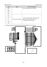
Connector pin
Description
1
-
Unused
2
-
Unused
3
B-Line
Data+ (twisted pair 1)
4
RTS
Request sending
5
GND_BUS
Isolation ground
6
+5V BUS
Isolated power supply of 5 V DC
7
-
Unused
8
A-Line
Data- (twisted pair 2)
9
-
Unused
Housing
SHLD
PROFIBUS cable shielding line
+5V and GND_BUS are bus terminators. Some devices, such as the optical transceiver (RS485),
may need to obtain power through these pins.
On some devices, the transmission and receiving directions are determined by RTS. In normal
applications, only A-Line, B-Line, and the shield layer need to be used.
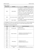
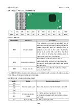
Indicator definition
Indicator No.
Definition
Function
LED1
State indicator
This indicator is on when the extension card is
establishing a connection with the control board;
it blinks periodically after the extension card is
properly connected to the control board (the
period is 1s, on for 0.5s, and off for the other
0.5s); and it is off when the extension card is
disconnected from the control board.
LED2
Online indicator
This indicator is on when the communication
card is online and data exchange can be
performed.
It is off when the communication card is not in
the online state.
LED3
Offline/Fault indicator
This indicator is on when the communication
card is offline and data exchange cannot be
performed.
It blinks when the communication card is not in
the offline state.
It blinks at the frequency of 1 Hz when a
configuration error occurs: The length of the user
parameter data set during the initialization of the
communication card is different from that during
the network configuration.

