DRV-28 inverter
s Basic operartion instructions
-114-
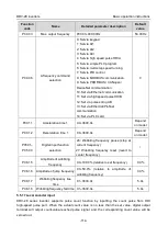
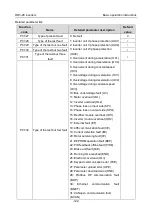
Function
code
Name
Detailed parameter description
Default
value
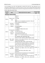
P00.03
Max. output frequency
P00.03–400.00Hz
50.00Hz
P00.06
A frequency command
selection
0: Set via keypad
1: Set via AI1
2: Set via AI2
3: Set via AI3
4: Set via high speed pulse HDIA
5: Set via simple PLC program
6: Set via multi-step speed running
7: Set via PID control
8: Set via MODBUS communication
9: Set via PROFIBUS / CANopen /
DeviceNet communication
10: Set via Ethernet communication
11: Set via high speed pulse HDIB
12: Set via pulse string AB
13: Set via EtherCat/Profinet
communication
14: Set via PLC card
0
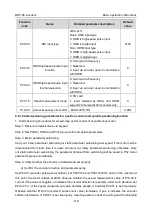
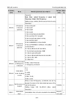
P00.11
Acceleration time 1
0.0–3600.0s
Depend
on model
P00.12
Deceleration time 1
0.0–3600.0s
Depend
on model
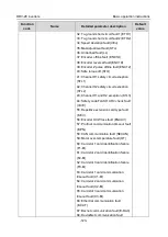
P05.01–
P05.09
Digital input function
selection
26: Wobbling frequency pause (stop at
current frequency)
27: Wobbling frequency reset (revert to
center frequency)
/
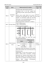
P08.15
Amplitude of wobbling
frequency
0.0–100.0% (relative to set frequency)
0.0%
P08.16
Amplitude of jump frequency
0.0–50.0% (relative to amplitude of
wobbling frequency)
0.0%
P08.17
Wobbling frequency rise
time
0.1–3600.0s
5.0s
P08.18
Wobbling frequency fall time 0.1–3600.0s
5.0s
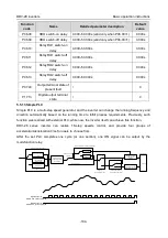
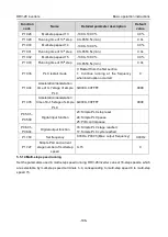
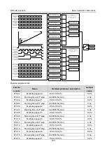
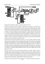
5.5.17 Local encoder input
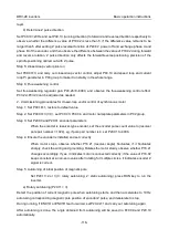
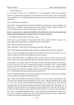
DRV-28 series inverter supports pulse count function by inputting the count pulse from HDI
high-speed pulse port. When the actual count value is no less than the set value, digital output
terminal will output count-value-reached pulse signal, and the corresponding count value will be
zeroed out.

