DRV-28 inverter
s Function parameter list
-146-
Function
code
Name
Detailed parameter description
Default
value
Modi
fy
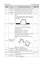
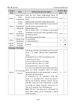
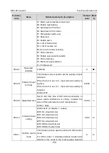
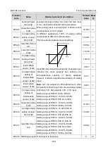
Output voltage
Output frequency
Linear type
Square type
Torque step-down V/F curve (1.3
th
order)
Torque step-down V/F curve (1.7
th
order)
Torque step-down V/F curve (2.0
nd
order)
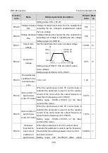
P04.01
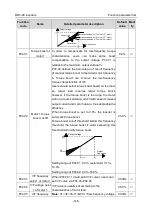
Torque boost of
motor 1
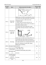
In order to compensate for low-frequency torque
characteristics, users can make some boost
compensation to the output voltage. P04.01 is
relative to the maximum output voltage V
b.
P04.02 defines the percentage of cut-off frequency
of manual torque boost to the rated motor frequency
f
b.
Torque boost can improve the low-frequency
torque characteristics of V/F.
Users should select torque boost based on the load,
eg, larger load requires larger torque boost,
however, if the torque boost is too large, the motor
will run at over-excitation, which will cause increased
output current and motor heat-up, thus degrading the
efficiency.
When torque boost is set to 0.0%, the inverter is
automatic torque boost.
Torque boost cut-off threshold: Below this frequency
threshold, the torque boost is valid, exceeding this
threshold will nullify torque boost.
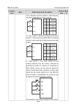
Output voltage
Output
frequency
Cut-off
boost
b
f
f
v
v
Setting range of P04.01: 0.0%: (automatic) 0.1%–
10.0%
Setting range of P04.02: 0.0%–50.0%
0.0%
○
P04.02
Motor 1 torque
boost cut-off
20.0%
○
P04.03
V/F frequency
point 1 of motor 1
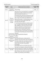
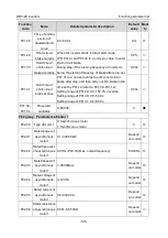
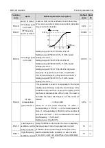
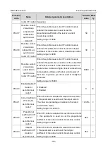
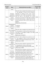
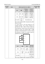
When P04.00 =1 (multi-point V/F curve), users can
set V/F curve via P04.03–P04.08.
V/F curve is usually set according to the
characteristics of motor load.
Note:
V1<V2<V3, f1<f2<f3. If low-frequency voltage
0.00Hz
○
P04.04
V/F voltage point
1 of motor 1
00.0%
○
P04.05
V/F frequency
0.00Hz
○

