DRV-28 inverter
s Extension cards
-304-
A.6.3 Ethernet communication card
–– AS28ETH0001
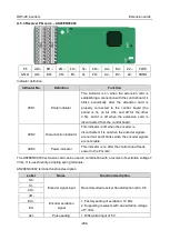
The AS28ETH0001 communication card adopts standard RJ45 terminals.
Indicator definition
Indicator No.
Definition
Function
LED1
State indicator
This indicator is on when the extension card is
establishing a connection with the control board;
it blinks periodically after the extension card is
properly connected to the control board (the
period is 1s, on for 0.5s, and off for the other
0.5s); and it is off when the extension card is
disconnected from the control board.
LED4
Power indicator
This indicator is on after the control board feeds
power to the communication card.
A.6.4 PROFIBUS-DP communication card
–– AS28PBS0001
CN1 is a 9-pin D-type connector, as shown in the following figure.
5
4
3
2
1
9
8
7
6


