DRV-28 inverter
s Basic operartion instructions
-64-
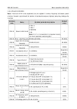
Function
code
Name
Detailed parameter description
Default
value
of motor 2
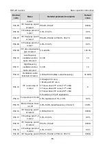
P04.21
V/F voltage point 3 of
motor 2
0.0%–110.0%
0.0%
P04.22
V/F slip compensation
gain of motor 2
0.0–200.0%
100.0%
P04.23
Low-frequency
oscillation control
factor of motor 2
0–100
10
P04.24
High-frequency
oscillation control
factor of motor 2
0–100
10
P04.25
Oscillation control
threshold of motor 2
0.00Hz–P00.03 (Max. output frequency)
30.00Hz
P04.26
Energy-saving run
0: No
1: Automatic energy-saving run
0
P04.27
Channel of voltage
setup
0: Keypad; output voltage is determined by P04.28
1: AI1
2: AI2
3: AI3
4: HDIA
5: Multi-step
6: PID
7: MODBUS communication
8: PROFIBUS/CANopen communication
9: Ethernet communication
10: HDIB
11: EtherCat/Profinet communication
12: PLC card
13: Reserved
0
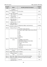
P04.28
Set voltage value via
keypad
0.0%–100.0% (rated motor voltage)
100.0%
P04.29 Voltage increase time
0.0–3600.0s
5.0s
P04.30
Voltage decrease
time
0.0–3600.0s
5.0s
P04.31
Output max. voltage P04.32
–100.0% (rated motor voltage)
100.0%
P04.32
Output min. voltage 0.0%
–P04.31 (rated motor voltage)
0.0%
P
0
Flux-weakening
coefficient in the
1.00–1.30
1.00


