DRV-28 inverter
s Function parameter list
-149-
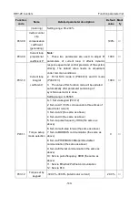
Function
code
Name
Detailed parameter description
Default
value
Modi
fy
△
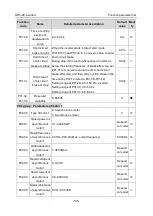
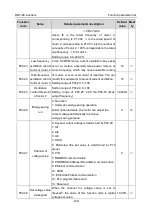
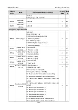
f=fb-n*p/60
where fb is the rated frequency of motor 2,
corresponding to P12.02; n is the rated speed of
motor 2, corresponding to P12.03; p is the number of
pole pairs of motor 2. 100% corresponds to the rated
slip frequency
△
f of motor 2.
Setting range: 0.0–200.0%
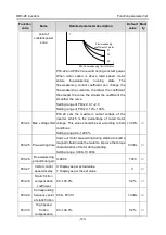
P04.23
Low-frequency
oscillation control
factor of motor 2
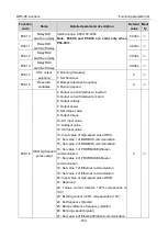
In the SVPWM mode, current oscillation may easily
occur on motors, especially large-power motors, at
some frequency, which may cause unstable running
of motors or even overcurrent of inverters. You can
modify this parameter to prevent current oscillation.
Setting range of P04.23: 0–100
Setting range of P04.24: 0–100
Setting range of P04.25: 0.00 Hz–P00.03 (Max.
output frequency)
10
○
P04.24
High-frequency
oscillation control
factor of motor 2
10
○
P04.25
Oscillation
control threshold
of motor 2
30.00Hz
○
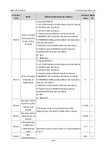
P04.26
Energy-saving
run
0: No action
1: Automatic energy-saving operation
Under light-load state, the motor can adjust the
output voltage automatically to achieve
energy-saving purpose
0
◎
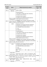
P04.27
Channel of
voltage setup
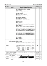
0: Keypad; output voltage is determined by P04.28
1: AI1
2: AI2
3: AI3
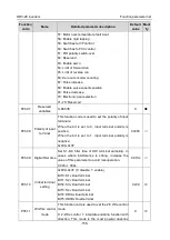
4: HDIA
5: Multi-step (the set value is determined by P10
group)
6: PID
7: MODBUS communication
8: PROFIBUS/CANopen/DeviceNet communication
9: Ethernet communication
10: HDIB
11: EtherCat/Profinet communication
12: PLC programmable card
13: Reserved
0
○
P04.28
Set voltage value
via keypad
When the channel for voltage setup is set to
"keypad", the value of this function code is digital
voltage set value.
100.0%
○

