DRV-28 inverter
s Basic operartion instructions
-104-
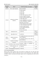
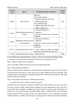
Function
code
Name
Detailed parameter description
Default
value
P06.08
HDO switch-on delay
0.000–50.000s (valid only when P06.00=1)
0.000s
P06.09
HDO switch-off delay
0.000–50.000s (valid only when P06.00=1)
0.000s
P06.10
Relay RO1 switch-on
delay
0.000–50.000s
0.000s
P06.11
Relay RO1 switch-off
delay
0.000–50.000s
0.000s
P06.12
Relay RO2 switch-on
delay
0.000–50.000s
0.000s
P06.13
Relay RO2 switch-off
delay
0.000–50.000s
0.000s
P07.40
Output terminal state of
present fault
/
0
P17.13
Digital output terminal
state
/
0
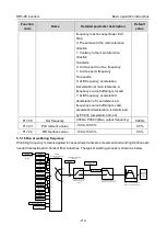
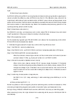
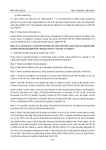
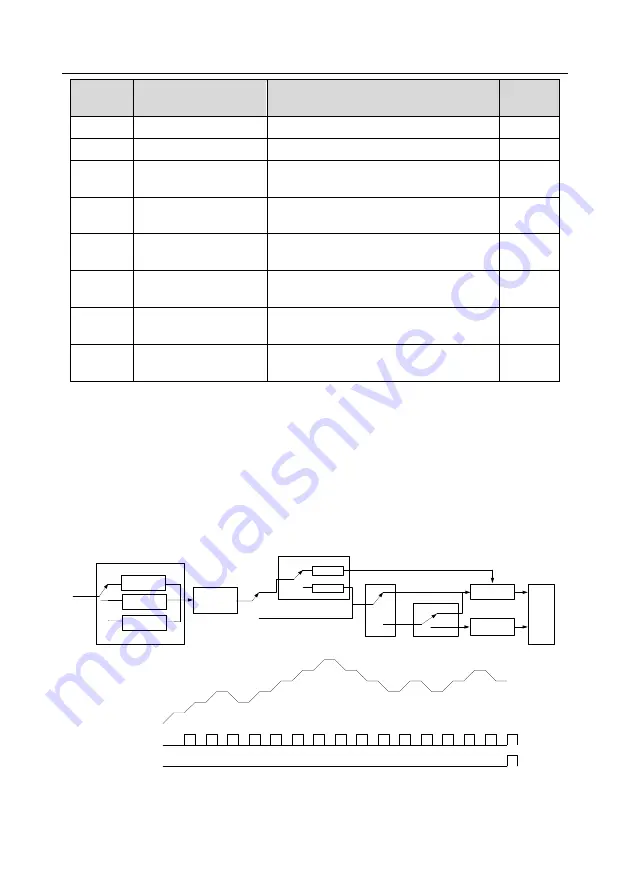
5.5.13 Simple PLC
Simple PLC is a multi-step speed generator, and the inverter can change the running frequency and
direction automatically based on the running time to fulfill process requirements. Previously, such
function was realized with external PLC, while now, the inverter itself can achieve this function.
DRV-28 series inverter can realize 16-step speeds control, and provide four groups of
acceleration/deceleration time for users to choose from.
After the set PLC completes one cycle (or one section), one ON signal can be output by the
multi-function relay.
Setup of running
parameters of each
PLC stage
Restart running
after the first
section
Continue running at
the frequency when
interruption occurred
Stop after running
once
Keep running in the
final value after
running once
Cyclic running
0
1
2
P10.00
(
simple PLC mode
)
PLC mode
0
1
0
1
0
1
Normal running
P10.01 (simple PLC memory selection)
No memory
after power off
Memory after
power off
P10.36
(PLC restart mode)
P17.00
Power cut during
running
Terminal function 23
Simple PLC stop reset
Set frequency
Digital output 16
Simple PLC state completed
Digital output 17
Simple PLC cycle completed


