


DRV-28 inverter
s Communication protocol
-259-
1#
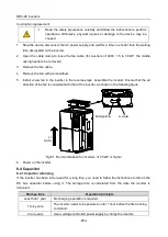
15#
32#
6
#
M
ain
co
ntro
l
dev
ice
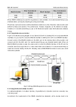
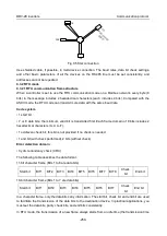
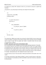
Fig 9.5 Star connection
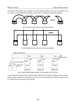
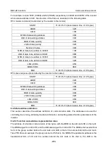
Use shielded cable, if possible, in multi-device connection. The baud rates, data bit check settings,
and other basic parameters of all the devices on the RS485 line must be set consistently, and
addresses cannot be repeated.
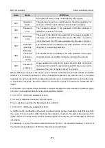
9.3.2 RTU mode
9.3.2.1 RTU communication frame structure
When a controller is set to use the RTU communication mode on a Modbus network, every byte (8
bits) in the message includes 2 hexadecimal characters (each includes 4 bits). Compared with the
ASCII mode, the RTU mode can transmit more data with the same baud rate.
Code system
• 1 start bit
• 7 or 8 data bits; the minimum valid bit is transmitted first. Each frame domain of 8 bits includes 2
hexadecimal characters (0–9, A–F).
• 1 odd/even check bit; this bit is not provided if no check is needed.
• 1 end bit (with check performed), 2 bits (without check)
Error detection domain
• Cyclic redundancy check (CRC)
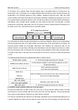
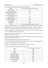
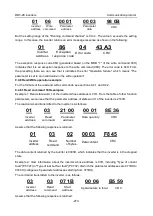
The following table describes the data format.
11-bit character frame (Bits 1 to 8 are data bits)
Start bit
BIT1
BIT2
BIT3
BIT4
BIT5
BIT6
BIT7
BIT8
Check
bit
End bit
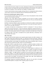
10-bit character frame (Bits 1 to 7 are data bits)
Start bit
BIT1
BIT2
BIT3
BIT4
BIT5
BIT6
BIT7
Check
bit
End bit
In a character frame, only the data bits carry information. The start bit, check bit, and end bit are used
to facilitate the transmission of the data bits to the destination device. In practical applications, you
must set the data bits, parity check bits, and end bits consistently.
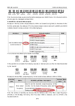
In RTU mode, the transmission of a new frame always starts from an idle time (the transmission time