Programming 5 - 3
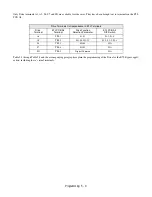
Only Drive terminals A1, A2, S6, S7 and SN are available for other uses. They have been brought out to terminals on the E7L
PCB A2:
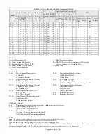
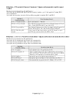
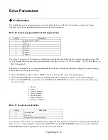
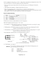
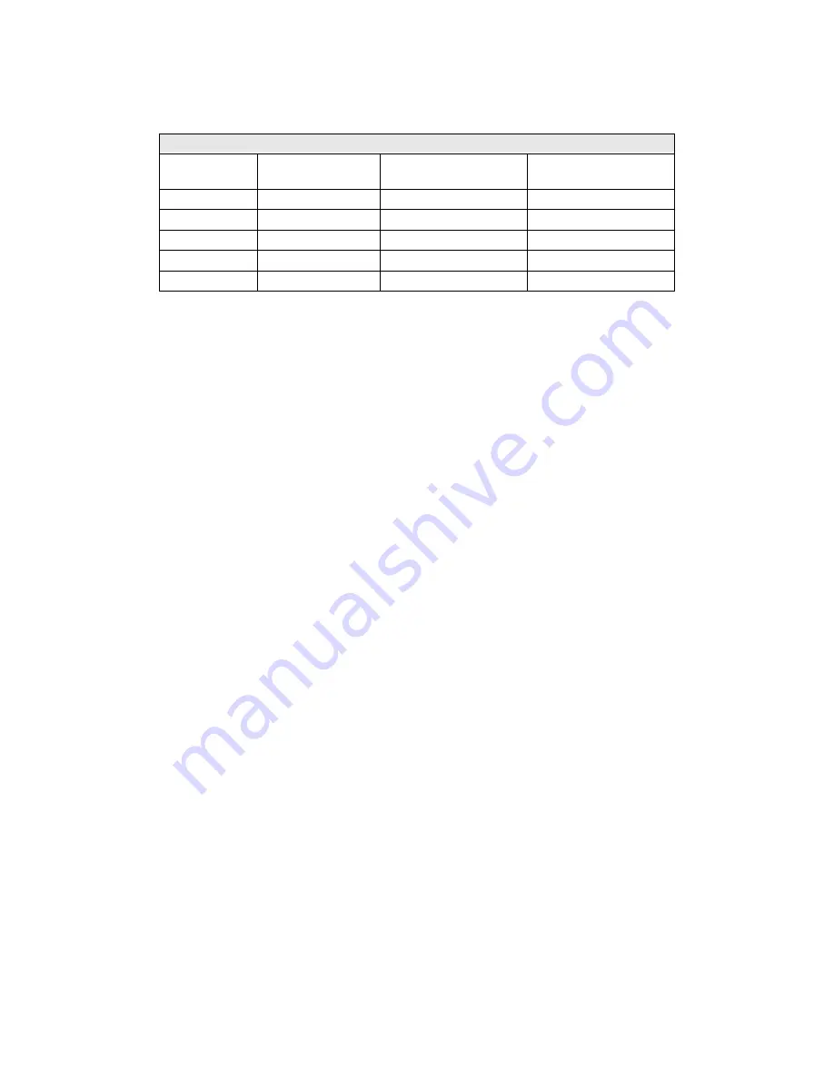
Table 5.1 through Table 5.4 and the accompanying paragraphs explain the programming of the Drive for the E7L Bypass appli-
cation, including these “virtual terminals.”
Drive Terminals Correspondence to E7L Terminals
Drive
Terminal
E7L PCB A2
Terminal
Drive Function
Selection Parameter
E7L PCB A2
DIP Switch
A1
TB3-3
b1-01
S1-3, S1-4
A2
TB3-3
H3-08, H3-13
S1-2, S1-3, S1-4
S6
TB5-5
H1-04
N/A
S7
TB5-4
H1-05
N/A
SN
TB5-2
Digital Common
N/A
Содержание E7LBA002
Страница 1: ...E7L Drive Bypass Technical Manual Model E7L Document Number TM E7L 01 ...
Страница 8: ...Introduction vi Notes ...
Страница 12: ...Table of Contents x Notes ...
Страница 54: ...Electrical Installation 2 22 Wiring Diagram ...
Страница 55: ...Electrical Installation 2 23 ...
Страница 87: ...Start Up and Operation 4 9 Notes ...
Страница 202: ...Diagnostic Troubleshooting 6 30 Notes ...
Страница 248: ...Capacity Related Parameters B 6 Notes ...
Страница 279: ...Communications D 27 Note ...
Страница 280: ...Communications D 28 ...
Страница 292: ...Spare Parts F 6 ...
Страница 304: ...Index 12 ...
Страница 305: ......


