Programming 5 - 39
d1 Preset References
d1-01 Frequency Reference 1
d1-02 Frequency Reference 2
d1-03 Frequency Reference 3
d1-04 Frequency Reference 4
Setting Range:
0.00 to E1-04 Value
Factory Default: d1-01 = 10.00 Hz
d1-02 = 6.00 Hz
d1-03 = 0.00 Hz
d1-04 = 0.00 Hz
d1-01 and d1-02 are special parameter settings required by the Bypass logic circuit. See Table 5.1.
Fig 5.20 Preset Reference Timing Diagram example
d1-17 Jog Frequency Reference
Setting Range:
0.00 to E1-04 Value
Factory Default: 6.00 Hz
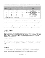
The Drive can be programmed to utilize digital inputs to change between four presets speeds and a jog speed. It is a two-step
process to set the Drive up for preset speeds. First, d1-01 through d1-04 and d1-17 must be programmed with the desired preset
speeds and the desired jog speed, respectively. Next, up to three of the Drive’s digital inputs (Terminals S3 through S7) need to be
programmed (via parameters H1-01 to H1-05) and wired (to normally open contacts) as Multi-step Speed Reference 1, Multi-step
Speed Reference 2, and Jog Frequency.
Table 5.8 Preset Speed Truth Table
Preset
Speed
Terminal
programmed as Multi-
step Reference 1
Terminal
programmed as Multi-
step Reference 2
Terminal
programmed as Jog
Reference
Details
1
OFF
OFF
OFF
Frequency Reference 1 (d1-01) or analog input A1†
(Determined by b1-01, see page 5-12)
2
ON
OFF
OFF
Frequency Reference 2 (d1-02) or analog input A2†
(Determined by H3-09, see page 5-57)
3
OFF
ON
OFF
Frequency Reference 3 (d1-03)
4
ON
ON
OFF
Frequency Reference 4 (d1-04)
5
-
-
ON*
Jog Frequency (d1-17)
*
The Jog Frequency input is given priority over the multi-step speeds.
†
Shown for H3-13 = “0: Main Fref TA1”, A1 and A2 are reversed if H3-13 = “1: Main Fref TA2”
RUN
Multi-step
Reference 1 Input
Multi-step
Reference 2 Input
Closed
Open
Closed
Open
Closed
Open
Closed
Open
Jog Input
Output
Speed
t
d1-01
d1-02
d1-03
d1-04
d1-17
Содержание E7LBA002
Страница 1: ...E7L Drive Bypass Technical Manual Model E7L Document Number TM E7L 01 ...
Страница 8: ...Introduction vi Notes ...
Страница 12: ...Table of Contents x Notes ...
Страница 54: ...Electrical Installation 2 22 Wiring Diagram ...
Страница 55: ...Electrical Installation 2 23 ...
Страница 87: ...Start Up and Operation 4 9 Notes ...
Страница 202: ...Diagnostic Troubleshooting 6 30 Notes ...
Страница 248: ...Capacity Related Parameters B 6 Notes ...
Страница 279: ...Communications D 27 Note ...
Страница 280: ...Communications D 28 ...
Страница 292: ...Spare Parts F 6 ...
Страница 304: ...Index 12 ...
Страница 305: ......


