


Electrical Installation 2 - 3
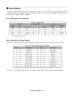
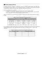
Field Wiring, Pressure Wire Connector, Wire Type, Range and Tightnening
Torque Specifications
IMPORTANT
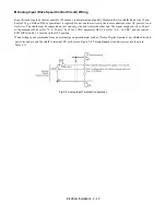
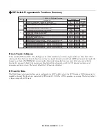
Determine the wire size for the main circuit so that line voltage drop is within 2% of the rated voltage. Line
voltage drop is calculated as follows:
Line voltage drop(V) =
√
3 x wire resistance (
Ω
/km) x wire length (m) x current (A) x 10
-3
WARNING
Prior to removing any protective cover or wiring any part of the Drive, remove all power sources, including
main input power and control circuit power. Wait a minimum of 5 minutes after power removal, before
removing any cover. The charge lamp located within the Drive should be off prior to working inside. Even if
the charge lamp is off, one must measure the AC input, output, and DC Bus potential to insure safe levels
prior to resuming work. Failure to adhere to this warning may result in personal injury or death.
208V
480V
MFG.
PART
NUMBER
WIRE SIZE
RANGE
(AWG)
MFG.
PART
NUMBER
WIRE SIZE
RANGE
(AWG)
208V
TIGHTENING
TORQUE
(LB.-IN.)
240V
480V
240V
D002
D003
D004
D007
D010
D016
D024
D030
D046
D059
D074
A002
A003
A004
A006
A009
A015
A022
A028
A042
A054
A068
A080
B001
B002
B003
B004
B007
B011
B014
B021
B027
B034
B040
B052
B065
B077
FAL36003
FAL36007
FAL36030
FAL36015
FAL36050
FAL36100
KAL36150
14 - 4
12 - 4
12 - 1/0
4 - 350 kcmil
35
35
80
250
TIGHTENING
TORQUE
(LB.-IN.)
D002
D003
D004
D007
D010
D016
D024
D030
D046
D059
D074
A002
A003
A004
A006
A009
A015
A022
A028
A042
A054
A068
A080
B001
B002
B003
B004
B007
B011
B014
B021
B027
B034
B040
B052
B065
B077
LR2 D13
LR2 D15
LR2 D25
LR2 D35
18 - 10
18 - 10
14 - 6
10 - 1/0
15
CURRENT
RATING
(AMPS)
3
7
15
30
50
100
150
=
= V (NEMA 1) OR B (NEMA 12)
V (NEMA 1) OR B (NEMA 12)
WHERE
WHERE
100
E7 BYPASS MODEL NO.
BASE NUMBER
E7L XXXX
E7 BYPASS MODEL NO.
BASE NUMBER
E7L XXXX
35
12 - 4
30
FAL36030
80
12 - 1/0
50
FAL36050
80
12 - 1/0
100
FAL36100
FAL36100
100
12 - 1/0
80
MFG.
PART
NUMBER
V0
V3
V4
V5
V6
CURRENT
RATING
(AMPS)
WIRE SIZE
RANGE
(AWG)
TIGHTENING
TORQUE
(LB.-IN.)
20
45
63
100
115
14 - 8
19
8 - 2/0
200
40
6 - 2
50
12 - 6
STANDARD INPUT DISCONNECT SWITCH
OPTIONAL MOTOR CIRCUIT PROTECTOR - OPTION C
WIRE SIZE
RANGE
(AWG)
TIGHTENING
TORQUE
(LB.-IN.)
V4
63
6 - 2
50
V6
115
8 - 2/0
200
14 - 10
35
8
6 - 4
45
GROUND LUG
12 - 1/0
80
CUSTOMER CONTROL WIRING
TERMINAL BLOCKS TB1 - TB5
WIRE SIZE
RANGE
(AWG)
TIGHTENING
TORQUE
(LB.-IN.)
4.4
22 - 14
MOTOR OVERLOAD RELAY
EARTH GND. WIRING
CUSTOMER A.C. LINE WIRING
CUSTOMER A.C. MOTOR WIRING
FOR 0 TO 100 AMPS, USE 60-75 C COPPER WIRE, AND ABOVE 100 AMPS, USE 75 C COPPER WIRE.
40
Содержание E7LBA002
Страница 1: ...E7L Drive Bypass Technical Manual Model E7L Document Number TM E7L 01 ...
Страница 8: ...Introduction vi Notes ...
Страница 12: ...Table of Contents x Notes ...
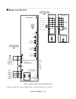
Страница 54: ...Electrical Installation 2 22 Wiring Diagram ...
Страница 55: ...Electrical Installation 2 23 ...
Страница 87: ...Start Up and Operation 4 9 Notes ...
Страница 202: ...Diagnostic Troubleshooting 6 30 Notes ...
Страница 248: ...Capacity Related Parameters B 6 Notes ...
Страница 279: ...Communications D 27 Note ...
Страница 280: ...Communications D 28 ...
Страница 292: ...Spare Parts F 6 ...
Страница 304: ...Index 12 ...
Страница 305: ......


