


Programming 5 - 13
If you want the Drive to follow the speed command set by the digital operator:
Use the
HAND
mode by pressing the
HAND key of the
HAND/OFF/AUTO
selector. The speed command can then be entered into the U1-01 monitor parameter in
the “-DRIVE-” Menu.
If you want the Drive to follow an AUTO analog speed command:
Connect a 0 – 10 VDC or a 4 – 20 mA speed command
signal to terminals TB3-3 (positive) and TB3-1 (common). Select the
AUTO
position of the Hand/Off/Auto selector.
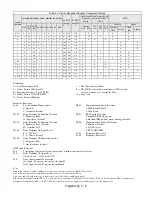
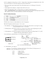
If you want the Drive to receive the speed command from serial communication:
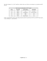
Set the parameters indicated in Table 5.2
for the desired serial communication option. Connect the RS-485/422 serial communications cable to terminals TB4-3 (R+),
TB4-4 (R-), TB4-1 (S+), and TB4-2 (S-) on the E7L PCB A2. The
HAND/OFF/AUTO
selector must be in the
AUTO
position.
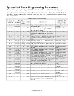
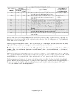
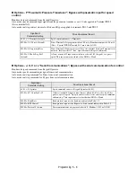
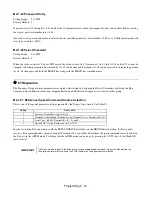
b1-02 Run Source
To successfully operate the Drive or Bypass and motor remotely, an external run command must be received by the Drive and
Bypass unit. Parameter b1-02 specifies from where the run command for the Drive will be accepted.
This parameter is by default set to “1: Terminals.” This setting is required by the Bypass logic circuit.
To issue a run command from the control panel:
Press the HAND key of the Hand/Off/Auto selector.
To issue a run command from a remote source, such as a BAS:
The Hand/Off/Auto selector must be in the
AUTO
position.
A contact closure between terminals TB1-2 and TB1-9 will control the Drive or Bypass start and stop operation.
To issue a run command via serial communication:
Set the parameters indicated in Table 5.2 for the desired serial
communication option. Connect the RS-485/422 serial communication cable to TB4-3 (R+), TB4-4 (R-), TB4-1 (S+), and
TB4-2 (S-) on the E7L PCB A2.
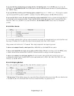
b1-03 Stopping Method
There are four methods of stopping the Drive when the Run command is removed.
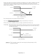
“0:Ramp to stop”:
When the Run command is removed, the Drive will decelerate the motor to 0 rpm. The rate of deceleration
is determined by the active deceleration time. The factory default Decel Time is in parameter C1-02.
Setting
Description
0
Operator
1
Terminals (
factory default
)
2
Serial Com
3
Option PCB
Setting
Description
0
Ramp to Stop (
factory default
)
1
Coast to Stop
2
DC Injection to Stop
3
Coast w/Timer
Содержание E7LBA002
Страница 1: ...E7L Drive Bypass Technical Manual Model E7L Document Number TM E7L 01 ...
Страница 8: ...Introduction vi Notes ...
Страница 12: ...Table of Contents x Notes ...
Страница 54: ...Electrical Installation 2 22 Wiring Diagram ...
Страница 55: ...Electrical Installation 2 23 ...
Страница 87: ...Start Up and Operation 4 9 Notes ...
Страница 202: ...Diagnostic Troubleshooting 6 30 Notes ...
Страница 248: ...Capacity Related Parameters B 6 Notes ...
Страница 279: ...Communications D 27 Note ...
Страница 280: ...Communications D 28 ...
Страница 292: ...Spare Parts F 6 ...
Страница 304: ...Index 12 ...
Страница 305: ......