Diagnostic & Troubleshooting 6 - 11
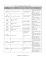
OL2
Inv Overloaded
Drive Overload
Designed to protect the Drive
The load is too large. The
cycle time is too short at the
accel/decel time.
Recheck the cycle time and the
size of the load as well as the
times set in C1-01 and C1-02.
The voltage of the V/F pattern
is high.
Review the V/F pattern
parameters, E1-01 thru E1-13.
The size of the Drive is small.
Change to a larger size Drive.
OL3
Overtorque Det 1
Overtorque Detection 1
Drive output current > L6-02 for more than
the time set in L6-03
Motor is overloaded.
Ensure the values in L6-02 and
L6-03 are appropriate.
Check application/machine
status to eliminate fault.
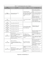
OPR
Oper Disconnect
Digital Operator Connection Fault
The Drive will stop if the digital operator is
removed when the Drive is commanded to
run through the digital operator.
The digital operator is not
attached or the digital opera-
tor connector is broken.
Attach the digital operator.
Check the digital operator
connector.
Verify the setting of o2-06.
OV
DC Bus Overvolt
DC Bus Overvoltage
208-240VAC: Trip point is
≥
400Vdc
480VAC: Trip point is
≥
800Vdc
High input voltage at R/L1,
S/L2 and T/L3.
Check the input circuit and
reduce the input power to within
specifications.
The deceleration time is set
too short.
Extend the time in C1-02.
Power factor correction
capacitors are being used on
the input to the Drive.
Remove the power factor
correction capacitors.
PF
Input Pha Loss
Input Phase Loss
Drive input power supply has an open phase
or has a large imbalance of input voltage.
Open phase on the input of the
Drive.
Check the input voltage.
Loose terminal screws at
R/L1, S/L2 or T/L3.
Tighten the terminal screws.
Momentary power loss
occurred.
Check the input voltage.
Input voltage fluctuation too
large.
Check the input voltage.
Parameter L8-06 value is set
incorrectly.
Adjust L8-06 according to your
application. The higher the value
the less sensitive it becomes.
PUF
DC Bus Fuse Open
DC Bus Fuse
Detects if the DC bus fuse has opened
Shorted output transistor(s) or
terminals.
Remove power from the Drive.
Disconnect the motor.
Perform the checks without
power in Table 6.6.
Replace the shorted
component(s).
Replace the defective fuse.
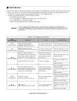
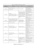
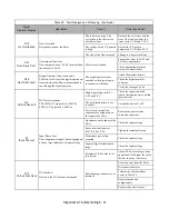
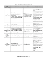
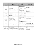
Table 6.3 Fault Displays and Processing (Continued)
Digital
Operator Display
Description
Cause
Corrective Action
Содержание E7LBA002
Страница 1: ...E7L Drive Bypass Technical Manual Model E7L Document Number TM E7L 01 ...
Страница 8: ...Introduction vi Notes ...
Страница 12: ...Table of Contents x Notes ...
Страница 54: ...Electrical Installation 2 22 Wiring Diagram ...
Страница 55: ...Electrical Installation 2 23 ...
Страница 87: ...Start Up and Operation 4 9 Notes ...
Страница 202: ...Diagnostic Troubleshooting 6 30 Notes ...
Страница 248: ...Capacity Related Parameters B 6 Notes ...
Страница 279: ...Communications D 27 Note ...
Страница 280: ...Communications D 28 ...
Страница 292: ...Spare Parts F 6 ...
Страница 304: ...Index 12 ...
Страница 305: ......

