


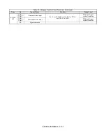


Electrical Installation 2 - 10
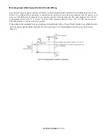
Building Automation system Run/Stop circuit:
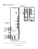
A control terminal block position (TB1, terminals 2 and 9) is provided to connect the Normally Open (NO) Run/Stop contact
from a BAS or other remote controller
for auto mode control.
There must be continuity between these terminals in order for the motor to run, in auto mode.
Safety Interlock Circuit:
A control terminal block position (TB1, terminals 1 and 9) is provided to connect the series circuit of Normally Closed (NC)
safety devices such as: freeze up thermostats, smoke/fire sensors, high pressure limits, temperature limits or vibration
detectors.
On power up the E7L will display a red “Safety Open” LED in the “System Status” area of the front control panel if a normally
closed “Safety Circuit” has not been installed between TB1-1 and TB1-9 on PCB A2. This condition will prevent Drive or
Bypass operation.
1 of 3 items needs to be done before the motor can be started:
1)
Install a NC “Safety Circuit” between TB1-1 and TB1-9 on PCB A2.
2)
Install a jumper between TB1-1 and TB1-9 on PCB A2. This method should be used if a “Safety Circuit” will be
added later in the installation.
3)
De-activate these terminals by moving DIP switch S2-7 to the ON position (toward the enclosure door). This solution
is only suggested if a “Safety Circuit” will never be applied to the drive system.
Building Automation System Interlock Circuit (Drive and Bypass enable input):
A control terminal block position (TB1, terminals 3 and 9) is provided to connect Normally Open (NO) enabling contacts such
as: damper end switches or occupied cycle timers.
When a Run command is received in HAND or AUTO mode, the E7L will display a red “Damper/BAS” LED in the “System
Status” area of the front control panel. This condition will prevent Drive or Bypass operation.
1 of 3 items needs to be done before the motor can be started:
1)
Install a “BAS Interlock Circuit” between TB1-3 and TB1-9 on PCB A2.
2)
Install a jumper between TB1-3 and TB1-9 on PCB A2. This method should be used if a “BAS Interlock Circuit” will
be added later in the installation.
3)
De-activate these terminals by moving DIP switch S2-8 to the ON position (toward the enclosure door). This solution
is only suggested if a “Safety Circuit” will never be applied to the drive system.
Содержание E7LBA002
Страница 1: ...E7L Drive Bypass Technical Manual Model E7L Document Number TM E7L 01 ...
Страница 8: ...Introduction vi Notes ...
Страница 12: ...Table of Contents x Notes ...
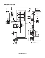
Страница 54: ...Electrical Installation 2 22 Wiring Diagram ...
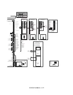
Страница 55: ...Electrical Installation 2 23 ...
Страница 87: ...Start Up and Operation 4 9 Notes ...
Страница 202: ...Diagnostic Troubleshooting 6 30 Notes ...
Страница 248: ...Capacity Related Parameters B 6 Notes ...
Страница 279: ...Communications D 27 Note ...
Страница 280: ...Communications D 28 ...
Страница 292: ...Spare Parts F 6 ...
Страница 304: ...Index 12 ...
Страница 305: ......