


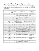


Programming 5 - 6
Definitions:
L = LonWorks Option Card
* = The Drive factory default
J = Native Protocol, Metasys N2
# = The H/O/A selector keys must have AUTO selected
P = Pneumatic Interface (3 to 15 PSIG)
to allow serial com. to control the Drive
U = Native Protocol, APOGEE FLN
@ = Don’t care
V = Native Protocol, Modbus
Parameter Reference:
b1-01:
Speed Command Input Source
H5-02:
Communication Speed Selection
0: Operator
3: 9600 Baud (default)
1: Terminals (default)
2: 4800 Baud
H1-02:
Drive Terminal S4 Function Selection
H5-07:
RTS Control Selection
3: Multi-step Ref 1
0: Disabled (RTS always on)
14: Fault Reset (default)
1: Enabled (RTS on only when sending) (default)
H1-03:
Drive Terminal S5 Function Selection
H5-08:
Communication Protocol Selection
3: Multi-step Ref 1 (default)
0: Modbus (default)
6C: Com/Inv Sel 2
1: N2 (Metasys)
H3-08:
Drive Terminal A2 Signal Level
2: FLN (APOGEE)
0: 0 - 10 VDC
d1-01:
Frequency Reference 1
2: 4 - 20 mA (default)
d1-02:
Frequency Reference 2
H3-09:
Drive Terminal A2 Function Selection
0: Frequency Bias
2: Aux Reference (default)
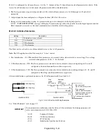
DIP Switch Reference:
S1-1:
Terminating resistor, always on for option L, otherwise on only if last device.
S1-2:
Drive Terminal A2 signal level
On = 4-20 mA Off = 0-10 VDC
S4-2:
Drive input terminal S4 operation
On = Input S4 operates inversely with input S5
Off = Inputs S4 and S5 operate independently
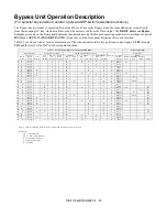
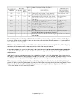
Notes:
Hand mode run/stop for Drive and Bypass is always via the front control panel HAND selector key.
Auto mode run/stop for Drive and Bypass without serial com. is from terminal TB1-2.
Auto mode run/stop with serial com. is from serial com. for both Drive and Bypass modes.
DIP switch configurable terminal TB3-3 is connected to Drive terminal A2 (the default). See Chapter 2 Table 2.8 for the alternate TB3-3 configuration.
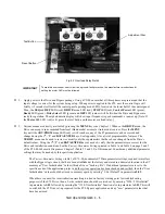
A Jumper is required from TB5-2 to TB5-7. This is essential for serial com. applications and benign for all other applications.
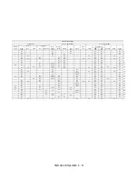
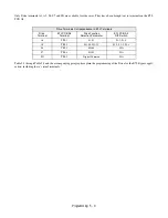
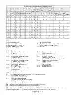
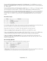
Table 5.2 Option Dependent Bypass Parameter Settings
Options
Specified
Parameters Effected by Options Specified and Settings
PCB DIP
Switch S1
1 2
PCB DIP
Switch S4
2
HAND Speed
Command
Source
Drive Terminal A2 Sig-
nal Level via TB3-3 or
TB5-9
AUTO
b1-01
H1-02
(S4)
H1-03
(S5)
H3-08 H3-09 H5-2 H5-7 H5-8
Keypad
d1-01 d1-02
4-20
mA
0-10
VDC
3-15
PSIG
Run/Stop
Speed
Terminal
TB1-2
Serial #
TB3-3
(A2)
Serial #
None
1*
14*
3*
2*
0
@
@
@
@
On*
Off*
X
X
X
X
None
1
14
3
0
0
@
@
@
@
Off
Off
X
X
X
X
P
1
14
3
2
0
@
@
@
@
On
Off
X
X
X
X
X
J
0
14
6C
@
@
3*
1*
1
Off*
@
Off
X
X
X
U
0
14
6C
@
@
2
1
2
Off
@
Off
X
X
X
V
0
14
6C
@
@
3
1
0*
Off
@
Off
X
X
X
J
0
3
6C
0
2*
3
1
1
Off
Off
On
X
X
X
X
U
0
3
6C
2
2
2
1
2
Off
On
On
X
X
X
X
V
0
3
6C
0
2
3
1
0
Off
Off
On
X
X
X
X
X
J & P
0
3
6C
2
2
3
1
1
Off
On
On
X
X
X
X
X
U & P
0
3
6C
2
2
2
1
2
Off
On
On
X
X
X
X
X
V & P
0
3
6C
2
2
3
1
0
Off
On
On
X
X
X
X
X
L
0
14
6C
@
2
3
0
0
On
@
Off
X
X
X
X
L
0
3
6C
0
2
3
0
0
On
Off
On
X
X
X
X
L & P
0
3
6C
2
2
3
0
0
On
On
On
X
X
X
X
X
Содержание E7LBA002
Страница 1: ...E7L Drive Bypass Technical Manual Model E7L Document Number TM E7L 01 ...
Страница 8: ...Introduction vi Notes ...
Страница 12: ...Table of Contents x Notes ...
Страница 54: ...Electrical Installation 2 22 Wiring Diagram ...
Страница 55: ...Electrical Installation 2 23 ...
Страница 87: ...Start Up and Operation 4 9 Notes ...
Страница 202: ...Diagnostic Troubleshooting 6 30 Notes ...
Страница 248: ...Capacity Related Parameters B 6 Notes ...
Страница 279: ...Communications D 27 Note ...
Страница 280: ...Communications D 28 ...
Страница 292: ...Spare Parts F 6 ...
Страница 304: ...Index 12 ...
Страница 305: ......