Programming 5 - 29
The analog feedback to the Drive for the PI control is via the Drive A2 terminal. The Drive must be programmed
(H3-09= “B: PI Feedback”) to use terminal A2 as feedback for the PI functionality of the Drive.
The PI setpoint can be configured to come from one of many different inputs or parameters. The table below describes the
options for originating the PI setpoint.
In some situations there are two feedback inputs. Air Handling Unit return fan speed control in a “volume matching” strategy
for building pressure control is an example. The Drive can be programmed to maintain a set differential between two
analog signals. If input A2 is configured as a “PI Differential Mode” (H3-09= “16: PI Differential”), then the Drive will
maintain a set difference between the measurements read on inputs TB3-3 (configured for Drive Terminal A1) and TB5-9
(Drive Terminal A2). This differential setpoint is programmed by parameter (b5-07).
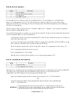
b5-01 PI Mode
The Drive can be used as a stand-alone PI controller. If PI functionality is selected by parameter b5-01, the Drive will adjust its
output to cause the feedback from a transmitter to match the PI setpoint (b5-19). The setting of b5-01 will determine whether
PI functionality is disabled (b5-01= “0: Disabled”), enabled (b5-01= “1: Enabled”), or enable with the output of the
PI function used to trim a Speed Command (b5-01= “3: Fref+PI”).
b5-02 Proportional Gain Setting
Setting Range:
0.00 to 25.00
Factory Default: 2.00
The proportional gain will apply a straight multiplier to the calculated difference (error) between the PI Setpoint and the
measured transmitter feedback at terminal A2. A large value will tend to reduce the error but may cause instability
(oscillations) if too high. A small value may allow to much offset between the setpoint and feedback (See Figure 5.16 on
following page).
b5-03 Integral Time Setting
Setting Range:
0.0 to 360.0 Seconds
Factory Default: 5.0 Seconds
Table 5.6 PI Setpoint Options
The PI Setpoint
will be read from:
If these conditions are true
Status of
b5-18
Status of
Modbus
Register
0Fh bit 1
Status of
b1-01
Parameter b5-19
= 1
N/A
N/A
Modbus Register
06H
= 0
ON
N/A
D1-01
= 0
OFF
= 0
Terminal A1
= 0
OFF
= 1
Serial Com.
= 0
OFF
= 2
Option PCB
= 0
OFF
= 3
Setting
Description
0
Disabled (
factory default
)
1
Enabled
3
Fref+PI
Содержание E7LBA002
Страница 1: ...E7L Drive Bypass Technical Manual Model E7L Document Number TM E7L 01 ...
Страница 8: ...Introduction vi Notes ...
Страница 12: ...Table of Contents x Notes ...
Страница 54: ...Electrical Installation 2 22 Wiring Diagram ...
Страница 55: ...Electrical Installation 2 23 ...
Страница 87: ...Start Up and Operation 4 9 Notes ...
Страница 202: ...Diagnostic Troubleshooting 6 30 Notes ...
Страница 248: ...Capacity Related Parameters B 6 Notes ...
Страница 279: ...Communications D 27 Note ...
Страница 280: ...Communications D 28 ...
Страница 292: ...Spare Parts F 6 ...
Страница 304: ...Index 12 ...
Страница 305: ......


