


Start Up and Operation 4 - 6
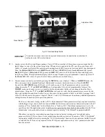
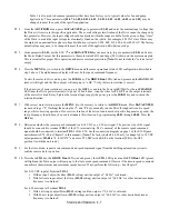
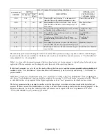
Fig 4.2 Overload Relay Detail
2.
Apply power to the Drive and Bypass package. Using a VOM, ensure that all three phases are present and that the
input voltage is correct for the system being set up. When power is applied to the E7L unit, the control logic will
briefly (<3 seconds) self test all the control panel operating mode LEDs, located on the lower half of the control panel.
Then, the SEQ and REF LEDs (red), DRIVE menu LED (red), STOP LED (red), Control Power LED (green),
Ready LED (green), Drive Select LED (green) and OFF LED (amber) will be lit when the Drive and Bypass are
ready for operation. The alpha/numeric display will show input frequency (speed command), at power up. [Note: If
the Motor O/L LED (red) is lit, press the reset button on the motor overload relay.]
3.
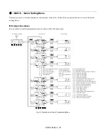
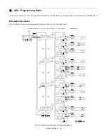
Various menus are directly available by pressing the MENU key (see Chapter 3). When in the DRIVE menu, the
Drive can accept a run command from local (Hand mode) or remote (Auto mode) sources. Press the MENU
key until the ADV/PRGM menu LED (red) is lit. From here, any of the E7 parameters can be accessed and
changed using the
,
, and DATA/ENTER keys. See Appendix A for a list of programmable features. The
VERIFY menu can be used to review or modify only those parameters that have been changed from the Drive’s
default values. Using the
,
, and DATA/ENTER keys as needed, verify that the parameters are correct for the
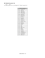
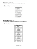
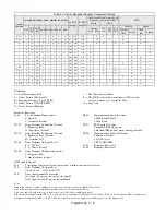
Drive and installation conditions. See the Factory Parameter Settings printed in Table 1 and Table 6 on page 2 and 3
of the E7L-00 Schematic Diagram or Chapter 5 (Table 5.1 and 5.2) of this manual. Consider any additional parameter
settings that may be needed by this specific application.
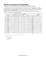
The Factory Parameter Settings, table 1 of E7L-00, documents E7 Drive parameter settings, required to interface
with the Bypass logic circuit, that have been established at the factory and stored in a dedicated location in the E7
memory as “User Initialization” values (think of it as a “back-up file”). If additional parameters are set to the
specific needs of the application project, and the system operation has been checked and verified, then the “User
Initialization” values should be stored in memory again by entering “1: Set Default” in parameter o2-03.
When there is a need for re-initialization (resetting to a known factory starting point for troubleshooting
purposes) of the E7L Drive, then a 2-wire initialization should be carried out by entering “2220: 2 Wire Initial”
in parameter A1-03, followed by entering the “1110: User Initialize” function, also in parameter A1-03. This will
re-establish the E7 Drive set-up required for the E7L Bypass application and any “user” parameter values that
have been stored.
IMPORTANT
To maintain overcurrent, short-circuit, and ground-fault protection, the manufacturer’s instructions for
setting the motor OLR must be followed.
Adjustment Dial
Test Button
Reset Button
Содержание E7LBA002
Страница 1: ...E7L Drive Bypass Technical Manual Model E7L Document Number TM E7L 01 ...
Страница 8: ...Introduction vi Notes ...
Страница 12: ...Table of Contents x Notes ...
Страница 54: ...Electrical Installation 2 22 Wiring Diagram ...
Страница 55: ...Electrical Installation 2 23 ...
Страница 87: ...Start Up and Operation 4 9 Notes ...
Страница 202: ...Diagnostic Troubleshooting 6 30 Notes ...
Страница 248: ...Capacity Related Parameters B 6 Notes ...
Страница 279: ...Communications D 27 Note ...
Страница 280: ...Communications D 28 ...
Страница 292: ...Spare Parts F 6 ...
Страница 304: ...Index 12 ...
Страница 305: ......


