Programming 5 - 63
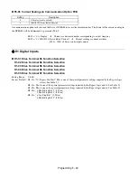
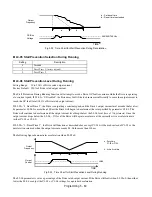
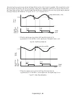
Fig 5.32 Time Chart for Stall Prevention During Deceleration
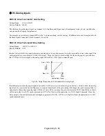
L3-05 Stall Prevention Selection During Running
L3-06 Stall Prevention Level During Running
Setting Range:
30 to 200% of Drive rated output current
Factory Default: 120% of Drive rated output current
The Stall Prevention During Running function will attempt to avoid a Drive OC fault occurrence while the Drive is operating
at a constant speed. If L3-05= “0: Disabled”, the Drive may fault if the load increases sufficiently to cause the output current to
reach the OC fault level (180% of Drive rated output current).
If L3-05= “1: Decel Time 1”, the Drive is outputting a constant speed, and the Drive’s output current level exceeds the level set
by parameter L3-06 for more than 100 ms the Drive will begin to decelerate at the rate specified by parameter C1-02. The
Drive will continue to decelerate until the output current level drops below the L3-06 level (less a 2% hysteresis). Once the
output current drops below the L3-06 – 2% level the Drive will begin to accelerate at the currently active acceleration rate
(either C1-01 or C1-03).
If L3-05= “2: Decel Time 2”, the Drive will function as described above except C1-04 will be used instead of C1-02 as the
deceleration rate used when the output current exceeds L3-06 for more than 100 ms.
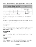
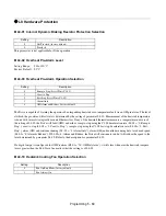
The following figure demonstrates acceleration when L3-05
≠
0.
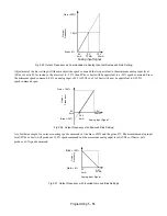
Fig 5.33 Time Chart for Stall Prevention Level During Running
The L3-06 parameter is set as a percentage of the Drive rated output current. If the Drive still faults when L3-05
≠
0, then either
lower the L3-06 or adjust the C1-02 or C1-04 settings for a quicker deceleration.
Setting
Description
0
Disabled
1
Decel Time 1 (
factory default
)
2
Decel Time 2
t
a
380/660/760 Vdc
t
Output
Frequency
DC Bus
Voltage
b
a - Set decel time
b - Decel time is extended
TIME
a
L3-06
t
Output
Frequency
Output
Current
b
a
- Decel time
C1-02 or C1-04.
b
– Active accel time
t
b
a
a - Decel time
C1-02 or C1-04
b - Active Accel time
TIME
Содержание E7LBA002
Страница 1: ...E7L Drive Bypass Technical Manual Model E7L Document Number TM E7L 01 ...
Страница 8: ...Introduction vi Notes ...
Страница 12: ...Table of Contents x Notes ...
Страница 54: ...Electrical Installation 2 22 Wiring Diagram ...
Страница 55: ...Electrical Installation 2 23 ...
Страница 87: ...Start Up and Operation 4 9 Notes ...
Страница 202: ...Diagnostic Troubleshooting 6 30 Notes ...
Страница 248: ...Capacity Related Parameters B 6 Notes ...
Страница 279: ...Communications D 27 Note ...
Страница 280: ...Communications D 28 ...
Страница 292: ...Spare Parts F 6 ...
Страница 304: ...Index 12 ...
Страница 305: ......

