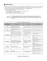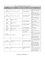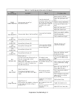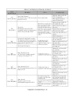
Diagnostic & Troubleshooting 6 - 2
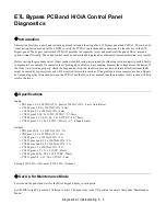
E7L Bypass PCB and H/O/A Control Panel
Diagnostics
Introduction
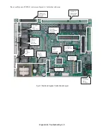
This section describes a quick and systemic approach in troubleshooting of an E7L Bypass panel and PCB A2. The only addi-
tional testing device needed will be a DVM to verify the PCB A2 interactions and connections to other devices in the E7L
Bypass panel. The bypass control card (PCB A2) provides the capability to test and monitor all the panel, Drive, user and
option wiring efficiently. Thus a bad control card can be detected and replaced, or eliminated from consideration, very rapidly.
Before starting the procedure below, follow routine troubleshooting tests around the offending section to detect possibly faulty
components. For example, if a contactor is not picking up or a blower is not running, measure the voltage across the device. If
the Drive is not working properly, check the keypad and verify that the Drive does not have an internal fault (external faults
might be caused by bypass system and will be resolved later in this section). If the problem is more complex, such as a Bypass
not responding or the interaction between the PCB A2 and the Drive is not normal, then the procedure in this section will help
resolve the issue.
Specifications
Inputs:
• TB1 pins 1-6: 6 x 24VDC±15% / 4mA or 120VAC±15% / 4mA, Auto-Detect
• CN104 pins 2-5: 4 x 120VAC±15% / 4mA
• CN109 pin 5: 1 x 120VAC±15% / 4mA
• CN110 pins 21-26: 6 x 3VDC-5.5VDC / 2.7-5mA
• CN102 pins 2, 3, 30, 32, 34: 5 x 15-27VDC / 4.2-7.5mA
• CN113 pins 2-13: 12 x 3-5VDC / 2mA (1, 6, 7, 8: Inputs Only)
Outputs:
• TB1 pins 10-14: 2 x 120VAC±15% / 5A
• TB2 pins 1-6: 2 x 120VAC±15% / 5A
• CN105 pin 1: 1 x 120VAC±15% / 5A
• CN107 pins 1 and 3: 2 x 120VAC±15% / 5A
• CN109 pins 1 and 3: 2 x 120VAC±15% / 5A
• CN108 pin 1: 1 x 120VAC±15% / 5A
• CN110 pins 1-17: 17 x 3-26VDC / 25mA
• CN102 pins 19-26, 28: 9 x 15-27VDC / 10mA
• CN113 pins 2-5, 9-13: 10 x 3-5VDC / 2mA
Fusing: F101/6.25A (10A-max), F102/0.25A (3A-max)
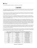
Set Up for Maintenance Mode
Power down the panel and wait for the Drive keypad display to extinguish.
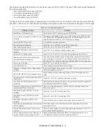
Set the DIP switch S2, position 3 (referred to as S2-3 from now on) to the ON position to activate the system “Maintenance
Mode.”
Содержание E7LBA002
Страница 1: ...E7L Drive Bypass Technical Manual Model E7L Document Number TM E7L 01 ...
Страница 8: ...Introduction vi Notes ...
Страница 12: ...Table of Contents x Notes ...
Страница 54: ...Electrical Installation 2 22 Wiring Diagram ...
Страница 55: ...Electrical Installation 2 23 ...
Страница 87: ...Start Up and Operation 4 9 Notes ...
Страница 202: ...Diagnostic Troubleshooting 6 30 Notes ...
Страница 248: ...Capacity Related Parameters B 6 Notes ...
Страница 279: ...Communications D 27 Note ...
Страница 280: ...Communications D 28 ...
Страница 292: ...Spare Parts F 6 ...
Страница 304: ...Index 12 ...
Страница 305: ......

