


Programming 5 - 2
Regarding Chapter 5
Standard LED Keypad Display and Optional LCD Keypad Display:
This programming chapter has been written to cover both the standard LED keypad display and the optional LCD keypad
display. When referring to the keypad display, the complete description of the parameter setting choices are presented for
clarity purposes. For example, one of the setting choices for parameter
b1-02
is “1: terminals.” Keep in mind that for the
standard LED keypad display, only the number of the choice will be shown. The optional LCD keypad display is required to
see the complete description.
Some sections of this chapter will apply only to the optional LCD operator, for example:
A1-00 Language
Selection
o1-05 to o1-08
LCD Display Selections
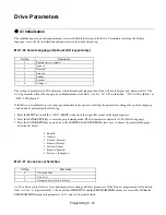
Programming Instructions for Individual Drive Parameters:
The discussions of individual Drive parameters in Chapter 5 are descriptive of the basic E7L unit without any options that
would effect the programming of the E7 Drive.
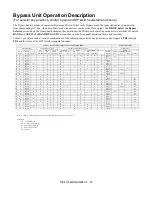
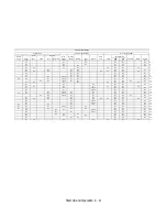
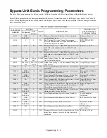
Programming for Various Configuration and Options:
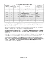
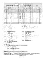
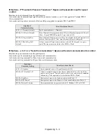
Tables 5.1 and 5.2 and the section titled “Discussion of Table 5.2 Option-Dependent Bypass Parameter Settings” provide
details of the unique programming required for the E7L Bypass applications of the Drive with various configurations of
options and sources for the control signals.
Tables 5.3 and 5.4 are similar but add PI control to the configuration possibilities.
Virtual Terminals
The Drive multi-function digital inputs and Drive analog inputs have (for the most part) become “virtual terminals” in the E7L
two contactor Bypass design.
The Bypass 120 VAC logic circuit is interconnected, via ribbon cable, with the Drive multi-function digital inputs and Drive
analog inputs to allow a single set of customer interface terminals to control both the Drive and Bypass circuits.
The Drive firmware however refers to these Drive terminals in order to program the functions of these inputs. The E7L
programming documentation and this manual then need to refer to these “virtual terminals” in Chapter 5 (programming) and
Appendix A (parameters). These “virtual terminals” are called out, for example, in Table 5.1
Bypass Parameter Settings
.
Drive terminals S1 through and including S5 are consumed by the needs of the bypass logic circuit. The programming of these
terminal functions is essential to the operation of the Drive and Bypass unit and is described in Tables 5.1 and 5.2.
Содержание E7LBA002
Страница 1: ...E7L Drive Bypass Technical Manual Model E7L Document Number TM E7L 01 ...
Страница 8: ...Introduction vi Notes ...
Страница 12: ...Table of Contents x Notes ...
Страница 54: ...Electrical Installation 2 22 Wiring Diagram ...
Страница 55: ...Electrical Installation 2 23 ...
Страница 87: ...Start Up and Operation 4 9 Notes ...
Страница 202: ...Diagnostic Troubleshooting 6 30 Notes ...
Страница 248: ...Capacity Related Parameters B 6 Notes ...
Страница 279: ...Communications D 27 Note ...
Страница 280: ...Communications D 28 ...
Страница 292: ...Spare Parts F 6 ...
Страница 304: ...Index 12 ...
Страница 305: ......