


Programming 5 - 17
b1-08 Run Command Selection During Programming
As a convenience to the user, the Drive will respond to a Run input even when the digital operator is being used to adjust
parameters. If it is necessary that external Run commands not be recognized while the Drive is being programmed, set
b1-08= “0: Disabled”.
b1-11 Drive Delay Time Setting
Setting Range:
0 to 600 Seconds
Factory Default: 0 Seconds
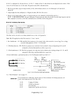
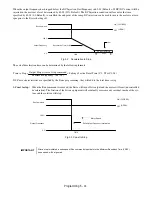
If a time is set into parameter b1-11, the Drive will delay executing any run command until the b1-11 time has expired.
During Drive delay time execution, the digital operator will display:
Both the ALARM and Run indicators will blink while the Drive waits to execute the Run command.
b2 DC Braking
The DC Braking Group contains parameters associated with the DC injection braking feature. Parameters involving the start-
ing frequency, current level, braking time, and motor pre heat current level are located here.
b2-01 DC Injection Braking Start Frequency
Setting Range: 0.0 to 10.0 Hz
Factory Default: 0.5 Hz
Parameter b2-01 sets the output frequency where the Drive begins DC Injection during Ramp to stop. in order to lock the rotor
of the motor and established the end point of the ramp. If b2-01 < E1-09 (Minimum Frequency), then DC Injection begins at
E1-09.
Parameter b2-01 also determines the output frequency that the Drive must be at or below before a Zero Speed condition is
considered true. This affects any digital output configured as a Zero Speed signal (H2-0x= “1: Zero Speed”).
Fig 5.6 DC Injection Braking During Stopping
Setting
Description
0
Disabled
1
Enabled (
factory default
)
DDLY
Waiting to RUN
Output Frequency
t
b2-01
DC injection
|
|
b2-04
ime
Содержание E7LBA002
Страница 1: ...E7L Drive Bypass Technical Manual Model E7L Document Number TM E7L 01 ...
Страница 8: ...Introduction vi Notes ...
Страница 12: ...Table of Contents x Notes ...
Страница 54: ...Electrical Installation 2 22 Wiring Diagram ...
Страница 55: ...Electrical Installation 2 23 ...
Страница 87: ...Start Up and Operation 4 9 Notes ...
Страница 202: ...Diagnostic Troubleshooting 6 30 Notes ...
Страница 248: ...Capacity Related Parameters B 6 Notes ...
Страница 279: ...Communications D 27 Note ...
Страница 280: ...Communications D 28 ...
Страница 292: ...Spare Parts F 6 ...
Страница 304: ...Index 12 ...
Страница 305: ......