Diagnostic & Troubleshooting 6 - 12
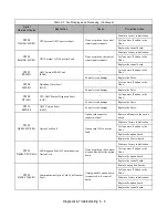
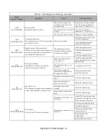
RH
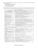
DynBrk Resistor
Dynamic Braking Resistor
The protection of the dynamic braking
resistor based on setting of L8-01
Overhauling load, extended
dynamic braking duty cycle,
defective dynamic braking
resistor.
Verify dynamic braking duty
cycle.
Monitor DC bus voltage.
Replace dynamic braking
resistor.
RR
DynBrk Transistr
Dynamic Braking Transistor
The dynamic braking transistor failed.
Shorted dynamic braking
transistor, high DC bus
voltage, defective dynamic
braking resistor.
Cycle power off and on to the
Drive.
Replace defective dynamic
braking transistor or resistor.
..
Monitor DC bus voltage.
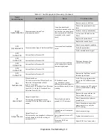
UV1
DC Bus Undervolt
DC Bus Undervoltage
The DC bus voltage is
≤
L2-05
208-240VAC: Trip point is
≤
190Vdc
480VAC: Trip point is
≤
380Vdc
Low input voltage at R/L1,
S/L2 and T/L3
Check the input circuit and
increase the input power to within
specifications.
The acceleration time is set too
short.
Extend the time in C1-01.
Voltage fluctuation of the input
power is too large.
Check the input voltage.
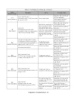
UV2
CTL PS Undervolt
Control Power Supply Undervoltage
Undervoltage of the control circuit when
running.
External load connected
pulling down the Drive power
supplies.
Cycle power off and on to the
Drive.
Repair or replace the Power PCB/
Gate Drive PCB.
Remove all control wiring and
test Drive.
UV3
MC Answerback
Soft Charge Circuit Fault
The pre-charge contactor opened while the
Drive was running.
Contacts on the soft charge
contactor are dirty and the soft
charge contactor does not
function mechanically.
Cycle power off and on to the
Drive.
Check the condition of the soft
charge contactor.
Repair or replace the Power PCB/
Gate Drive PCB.
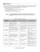
WARNING
Some features within the PI function group cause the Drive to shut down momentarily (e.g. Sleep Function,
Snooze Function, Feedback Loss feature etc.) Upon recovery from the conditions that activate these features,
the Drive may start unexpectedly. Therefore, when enabling these features take appropriate measures to
notify personnel working with this equipment that unexpected starting may occur.
Table 6.3 Fault Displays and Processing (Continued)
Digital
Operator Display
Description
Cause
Corrective Action
Содержание E7LBA002
Страница 1: ...E7L Drive Bypass Technical Manual Model E7L Document Number TM E7L 01 ...
Страница 8: ...Introduction vi Notes ...
Страница 12: ...Table of Contents x Notes ...
Страница 54: ...Electrical Installation 2 22 Wiring Diagram ...
Страница 55: ...Electrical Installation 2 23 ...
Страница 87: ...Start Up and Operation 4 9 Notes ...
Страница 202: ...Diagnostic Troubleshooting 6 30 Notes ...
Страница 248: ...Capacity Related Parameters B 6 Notes ...
Страница 279: ...Communications D 27 Note ...
Страница 280: ...Communications D 28 ...
Страница 292: ...Spare Parts F 6 ...
Страница 304: ...Index 12 ...
Страница 305: ......

