


Electrical Installation 2 - 8
Control Wiring
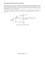
Bypass Field Control Wire Landing
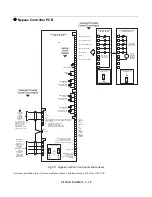
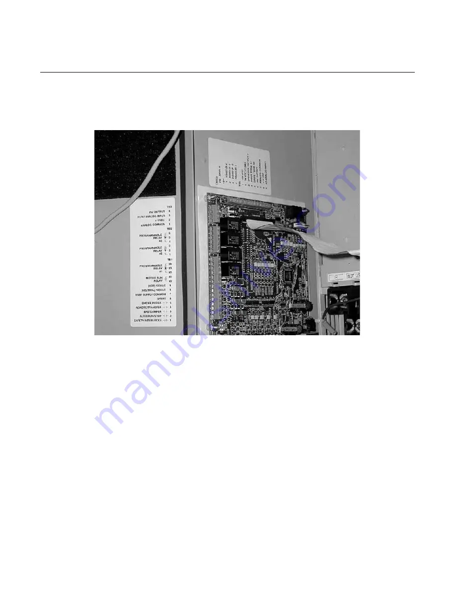
The Bypass field control wiring is terminated on the control PCB A2, Terminal blocks TB1 through TB5. The terminal desig-
nations are labeled on the enclosure, adjacent to PCB A2 (see Figure 2.6). Route the control wiring as shown in Figure 2.5.
Fig 2.6 TB1 Control Terminal Locations, All Models
Содержание E7LBA002
Страница 1: ...E7L Drive Bypass Technical Manual Model E7L Document Number TM E7L 01 ...
Страница 8: ...Introduction vi Notes ...
Страница 12: ...Table of Contents x Notes ...
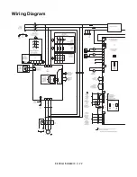
Страница 54: ...Electrical Installation 2 22 Wiring Diagram ...
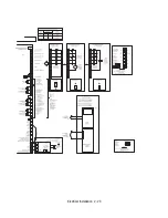
Страница 55: ...Electrical Installation 2 23 ...
Страница 87: ...Start Up and Operation 4 9 Notes ...
Страница 202: ...Diagnostic Troubleshooting 6 30 Notes ...
Страница 248: ...Capacity Related Parameters B 6 Notes ...
Страница 279: ...Communications D 27 Note ...
Страница 280: ...Communications D 28 ...
Страница 292: ...Spare Parts F 6 ...
Страница 304: ...Index 12 ...
Страница 305: ......