


Programming 5 - 55
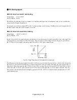
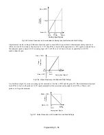
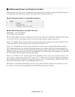
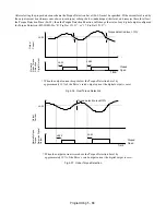
Fig 5.25 Output Frequency as Commanded via Analog Input with Increased Gain Setting
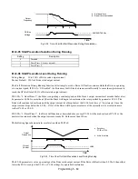
Adjustment of the bias setting will likewise adjust the speed command that is equivalent to the minimum analog input level
(0Vdc or 4mA). If, for instance, the bias is set to –25%, then 0Vdc or 4mA will be equivalent to a –25% speed command. Since
the minimum speed command is 0% an analog input of 2.5 to10Vdc or 8 to 20mA will now be equivalent to 0-100%
speed command span.
Fig 5.26 Output Frequency with Reduced Bias Setting
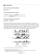
As a further example, for an inverse-acting speed command, set the bias= 100% and the gain= 0%. The minimum analog input
level (0Vdc or 4mA) will produce a 100% speed command and the maximum analog input level (10Vdc or 20mA) will
produce a 0% speed command.
Fig 5.27 Output Frequency with Inverted Gain and Bias Settings
4mA
20mA
0V
10V
Bias = 0%
O
u
tput
Freq
uenc
y
Analog Input Level
Gain =200%
100%
Analog Input Signal
5V
12mA
0V
4mA
10V
20mA
Gain = 100%
Bias = -25%
Out
put
Frequenc
y
Analog Input Level
2.5V
8mA
Analog Input Signal
20mA
4mA
0V
10V
Gain = 100%
Bias = 0%
Out
p
ut
F
req
uen
c
y
Analog Input Level
Analog Input Signal
Bias
Gain
Содержание E7LBA002
Страница 1: ...E7L Drive Bypass Technical Manual Model E7L Document Number TM E7L 01 ...
Страница 8: ...Introduction vi Notes ...
Страница 12: ...Table of Contents x Notes ...
Страница 54: ...Electrical Installation 2 22 Wiring Diagram ...
Страница 55: ...Electrical Installation 2 23 ...
Страница 87: ...Start Up and Operation 4 9 Notes ...
Страница 202: ...Diagnostic Troubleshooting 6 30 Notes ...
Страница 248: ...Capacity Related Parameters B 6 Notes ...
Страница 279: ...Communications D 27 Note ...
Страница 280: ...Communications D 28 ...
Страница 292: ...Spare Parts F 6 ...
Страница 304: ...Index 12 ...
Страница 305: ......