


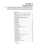


Programming 5 - 5
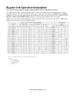
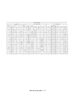
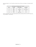
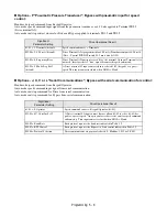
The shaded Bypass Parameter Settings in Table 5.1 document Drive parameter settings, required to interface with the Bypass
logic circuit, that have been established at the factory and stored in a dedicated location in the memory as “User Initialization”
values (think of it as a “back-up file”).
Table 5.1 is also used to document parameters that have been factory set, for convenience, to typical values for fan and pump
applications. These parameters may be changed to meet the needs of the specific application.
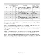
If additional parameters are set to the specific needs of the application project, and the system operation has been checked and
verified, then the “User Initialization” values should be stored in memory again by selecting and entering “1: Set Default” in
parameter
o2-03
.
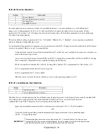
When there is a need for re-initialization of the “user” parameters (re-setting to the “User Initialization” values) of the Bypass
unit, then a “User Initialization” function should be carried out by selecting “1110: User Initialize” in parameter
A1-03
. This will
re-establish the drive set-up required for the Bypass application and any “user” parameter values that have been stored.
The factory parameter settings required to interface with the bypass logic circuit have also been stored in the digital keypad
memory. If there is a need for re-initialization (re-setting to a known factory starting point for trouble-shooting purposes) of the
Bypass unit, then the “back-up file” in the digital keypad memory can be copied to the drive. In parameter o3-01 select
“2: OP->INV WRITE” to carry out the copy function.
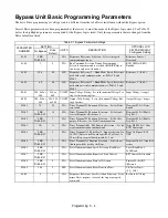
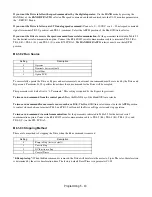
PARAMETER
NUMBER
SETTING
UNITS
DESCRIPTION
OPTIONAL LCD
KEYPAD DISPLAY
For Bypass Setting
For Bypass
Drive
Default
L5-01
10.0
0
N/A
Number of Re-start Attempts – Sets the number of
times the Drive will perform an automatic re-start
Num of Restarts / (0-10)
L5-03
10
180
SEC
Maximum Restart Time After Fault – If not success-
fully started after this time, restart attempts stop and
Drive faults
Max Restart Time /
(.5-600.0)
02-01
0
1
N/A
Drive Local/Remote Key Function Selection – Enables
or Disables the Local/Remote Key
Local/Remote Key/
Disabled
o2-02
0
1
N/A
Drive OFF Key Function During Auto Run – Enables
or disables the Off key.
Oper STOP Key /
Disabled
o2-03
1
0
N/A
User Parameter Default Value – Stores Bypass
parameter settings for recall via A1-03 = “1110: User
Initialize”
User Defaults/
Set Defaults
o2-15
0
1
N/A
Drive Hand Key Function Selection - Enables or dis-
ables the Hand and Auto keys (optional LCD operator)
Hand Key / Disabled
o3-02
1
0
Read Allowed Selection – Enables or disables keypad
copy functions
Read Allowable / Enabled
Table 5.1 Bypass Parameter Settings (Continued)
Содержание E7LBA002
Страница 1: ...E7L Drive Bypass Technical Manual Model E7L Document Number TM E7L 01 ...
Страница 8: ...Introduction vi Notes ...
Страница 12: ...Table of Contents x Notes ...
Страница 54: ...Electrical Installation 2 22 Wiring Diagram ...
Страница 55: ...Electrical Installation 2 23 ...
Страница 87: ...Start Up and Operation 4 9 Notes ...
Страница 202: ...Diagnostic Troubleshooting 6 30 Notes ...
Страница 248: ...Capacity Related Parameters B 6 Notes ...
Страница 279: ...Communications D 27 Note ...
Страница 280: ...Communications D 28 ...
Страница 292: ...Spare Parts F 6 ...
Страница 304: ...Index 12 ...
Страница 305: ......