Watkiss DigiVAC Скачать руководство пользователя страница 21

Service Procedures

 • 

General Service Procedures

Watkiss DigiVAC Service Manual - Issue 2 - 29/11/04

15

3.1.4  Removing L/H Side Plates

For many service procedures it is necessary to remove the joint, coupling and
clamp plates from the L/H side of the machine in order to access other parts.

Procedure

1. Disconnect the DigiVAC from the mains power supply.
2. Remove the side covers from the top module and bin modules on the L/H

side of the machine. 

only:

 carefully disconnect the 50-way cable and earth lead

from behind the screen mounting panel.

DigiVAC standard only:

 Remove the control panel (see Section 3.3.1).

3. Undo the retaining screws and remove the joint plates from between the

top and bin modules.

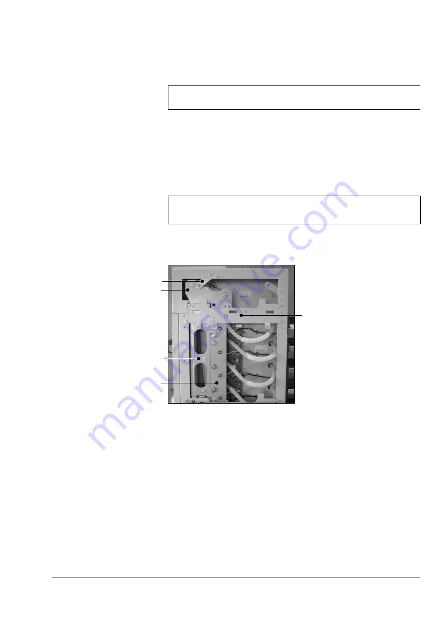
Figure 3:3   Removing L/H Side Plates

4. Pivot the L/H top module side cover fixing tang bracket away from the top

conveyor coupling plate by undoing one retaining screw and loosening the
other. 

5. Undo the retaining screws and remove the top conveyor coupling plate. 
6. Undo the retaining screws and remove the bin module feeder belt clamp

plates.

7. Undo the retaining screws and remove the feeder clutch plates.
8. Continue with other service procedures as necessary.

3.1.5  Bin Addressing

After bin modules have been installed, or if the feeder control PCB has been
changed, the bins need to be addressed.

PARTS REQUIRED

TOOLS REQUIRED

None

3mm Allen Key

Note: 
The number of joint plates, clutch plates and belt clamp plates that need to be 
removed will depend on the position of the part requiring servicing. 

Side Cover Fixing Tang

Joint Plate

Top Conveyor Coupling Plate

Feeder Belt Clamp Plate

Feeder Clutch Plate

Содержание DigiVAC

Страница 1: ...ss DigiVAC Service Manual Issue Date 29 November 2004 Issue Number 2 Part Number 969 251 Watkiss Automation Ltd 1 Blaydon Road Middlefield Industrial Estate Sandy Bedfordshire SG19 1RZ U K Tel 44 0 17...

Страница 2: ...Reserved Reproduction adaptation or translation without prior written permission is prohibited except as allowed under the copyright laws Warranty The information contained in this document is subject...

Страница 3: ...1 General Service Procedures 13 3 1 1 Bin Test Mode 13 3 1 2 Removing the Rear Conveyor Assembly 14 3 1 3 Removing the Rear Deflector Plates 14 3 1 4 Removing L H Side Plates 15 3 1 5 Bin Addressing...

Страница 4: ...lers 35 3 6 Base Module 36 3 6 1 Replacing Drive Motor 36 3 6 2 Checking the Vacuum Pressure 38 3 6 3 Replacing the Vacuum Pump Motor 38 3 6 4 Replacing Motor Tacho Sensor 39 3 6 5 Replacing or Cleani...

Страница 5: ...IG 0000149 67 4 1 5 DigiVAC High Voltage Connections S Nos DIG 0000150 onwards 68 4 1 6 DigiVAC High Voltage Connections S Nos DIG 0000150 onwards 69 4 1 7 DigiVAC Standard Low Voltage Connections S N...

Страница 6: ...ction 106 5 2 DigiVAC Pre Delivery Inspection 110 6 Routine Maintenance 6 1 DigiVAC Routine Maintenance Schedule 113 6 2 DigiVAC X Jogger Routine Maintenance Schedule 114 7 Installation 7 1 Prior to I...

Страница 7: ...950 042 DigiVAC Rear Door Gear Cover If a service procedure requires the DigiVAC to be operated with the rear door open exposed gears are a hazard to the engineer This gear cover MUST be fitted 950 04...

Страница 8: ...he correct size before making any changes to the machine 1 1 5 Metric and Imperial measurements In most cases metric measurements and specifications are used in this manual A conversion chart is inclu...

Страница 9: ...2 bins It has a 5 digit counter with total count and preset count Compatible accessories X Jogger Straight Jogger BookMaster range of bookletmakers and trimmers 1 2 2 DigiVAC The DigiVAC is available...

Страница 10: ...er Service Manual part no 969 240 Automatic Stitch Fold Trim part no 969 270 SpineMaster Service Manual part no 969 230 Module Address The module address is used by the system software to iden tify an...

Страница 11: ...032 165 DBAS DigiVAC Base Module 200V 50 60 Hz 210V 60Hz 230V 50Hz 240V 50Hz 032 200 032 201 032 203 032 204 17 DXJG DigiVAC X Jogger 032 320 DigiVAC X Jogger including Front Outfeed Conveyor 032 321...

Страница 12: ...ciated electronics required for the DigiVAC s operation The base also includes a toroidal transformer on all except 240V machines see Section 4 1 2 on 65 for details of transformer tappings The DigiVA...

Страница 13: ...eed system in each bin The feed timing is controlled by a clutch on the clutch drive shaft of each bin A tachometer located on the end of the drive motor shaft provides the master timing signal for th...

Страница 14: ...i Tower Systems Multi tower systems are only possible with the Digi VAC Two DigiVAC towers can be linked to give up to 24 bins The top module of Tower B includes connecting bridge which transports pap...

Страница 15: ...up on the bin as a Jam PSU VOLTAGE ERROR 28v message is displayed No Jog or Oscillate Function is available DigiVAC Base Power PCB F4 No Jog function No Power to Stacker mes sage displayed No Oscillat...

Страница 16: ...10 Watkiss DigiVAC Service Manual Issue 2 29 11 04 Overview Fuses...

Страница 17: ...ical Neon 952 060 Spanner Combination 5 5mm 952 062 Spanner Combination 7mm M4 952 063 Spanner Combination 8mm M5 952 066 Spanner Combination 10mm M6 952 067 Spanner Combination 13mm M8 952 002 Specia...

Страница 18: ...951 007 Loctite 242 thread locking compound 951 023 Loctite Retainer 641 weak retaining compound Light Oil SA30 40 2 3 Service Aids WATKISS PART NO DESCRIPTION Digital Multi Meter 370 052 Bin Sensor C...

Страница 19: ...e bypassed Note the gear cover must also be fitted 3 1 1 Bin Test Mode For some service procedures it is necessary or helpful to put individual bin modules into test mode This allows some functions to...

Страница 20: ...belts are correctly aligned 3 1 3 Removing the Rear Deflector Plates For many service procedures it is necessary to remove the rear deflector plates Figure 3 2 Rear Deflector Plates There are two pos...

Страница 21: ...igure 3 3 Removing L H Side Plates 4 Pivot the L H top module side cover fixing tang bracket away from the top conveyor coupling plate by undoing one retaining screw and loosening the other 5 Undo the...

Страница 22: ...h off and switch on the power again to automatically initialise the bins Ensure that the correct number of bins is shown on the GUI mimic diagram 3 1 6 PCB Removal Fitting and Adjustments General Comm...

Страница 23: ...cure the top assembly pivot shaft 5 Lift the assembly clear and withdraw the pivot shaft 6 The belts can now be replaced 7 Reassembly is the reverse of disassembly 3 3 1 Removing the Control Panel Dig...

Страница 24: ...key code of the key being pressed If no buttons are pressed this should be 00 To end the test press twice Bin Cycle Access The display will clear then on pushing the on off but ton of a bin the cycles...

Страница 25: ...unit CPU Figure 3 5 GUI Touch Screen 3 4 2 Operation Operating instructions are included in the relevant operating manual They are not repeated here in this Service Manual Chapter 6 explains how to p...

Страница 26: ...nt where it is touched If it is not calibrated some menus on the screen may appear to be unresponsive or react off centre Procedure 1 With the DigiVAC switched on touch the Stop button positioned abov...

Страница 27: ...DARKER MG FEEDER INFO MGC CLEANING MGL TOTALSET LIMITER View only when limit reached View only add 100 sets if at limit View only add 5000 sets if at limit MO MACHINE OPTIONS MOO REMOTE OUTPUT View o...

Страница 28: ...of the separator adjustment shaft raising and lowering the separator lever will help identify the correct linkage The linkage is retained by an E clip onto the 8mm actuation shaft Remove the E clip a...

Страница 29: ...3 10 Feed Band Removal 4 The feed band is held across the central manifold under tension by two metal shafts push the shorter shaft away from the moulding then roll it upwards to release the tension i...

Страница 30: ...ing is located fully onto the feeder stub shaft and that the bin feeder drive belt see Figure 3 14 on page 30 is correctly wrapped around the clutch pulley 11 Re fit the anti static bearing and the tw...

Страница 31: ...tor plate from the appropriate bin and the two bins below 5 Remove the appropriate conveyor shaft by pushing it to the left against the spring pressure and lifting the R H end clear Repeat on the bin...

Страница 32: ...et Secure them with new cable ties 17 Connect the end of the cable assembly into the bin control PCB and secure the cable at the correct length to the hexagonal stand off post 18 Re fit the conveyor s...

Страница 33: ...t require emitter sensor calibration 9 When all emitter sensors are calibrated replace the rear conveyor and side covers 10 Test machine operation 3 5 7 Replacing Tray Sensor The tray sensor is locate...

Страница 34: ...metal contact is facing to the front of the machine towards the bins 10 Switch on the mains power and test that the sensor is operating correctly 11 Re fit the side cover 3 5 8 Set the Separator Stop...

Страница 35: ...ply pipe assembly out through the machine side frame 5 Separate the two halves of the filter housing by holding the outer half whilst twisting and pulling the inner half with the elbow attached 6 Clea...

Страница 36: ...hat the valve is positioned with the indicator arrow pointing to wards the vacuum supply manifold towards the bins 2 Re fit the valve in the opposite order to removal 3 5 11 Replacing Bin Feeder Drive...

Страница 37: ...aft which in turn causes the feeder band to rotate when the clutch is not engaged If the belts are too slack they can jump teeth over the pulleys or induce an offset between sheets in the set It is al...

Страница 38: ...sh the separator lever to the top position and operate the feed clutch by pressing the bin on off button Watch the feeder drive belt to see if it tracks off the clutch pulley towards the separator adj...

Страница 39: ...on the pulleys it is recommended that this be the standard tension setting Procedure 1 Disconnect the DigiVAC from the mains power supply 2 Remove all the bin module side covers from the L H side of t...

Страница 40: ...nveyor section 7 Replace the conveyor belts and reassemble the conveyor in the reverse order to the disassembly procedure 3 5 16 Replacing Worn Conveyor Wheels Worn or dirty conveyor wheels will resul...

Страница 41: ...15 Replace the rear deflector plates and the rear conveyor assembly 16 Close the rear door and test the machine function 3 5 17 Removing the Pinch Wheel Idlers The pinch wheel idlers can be removed if...

Страница 42: ...sing can now be removed from behind the metalwork 3 6 1 Replacing Drive Motor Procedure 1 Disconnect the DigiVAC from the mains power supply 2 Remove the rear cover assembly Undo and remove 4 x M5 but...

Страница 43: ...otor to it s highest position and remove the drive belt Then let the motor down to it s lowest position 8 Remove the motor and mounting plate if possible enlist the help of an assistant to support the...

Страница 44: ...n 100 and 130 mBar For Serial Nos DIG 0000150 onwards this should be 150 mBar 3 6 3 Replacing the Vacuum Pump Motor The vacuum pump for the DigiVAC is in the base module If the pump becomes worn or fa...

Страница 45: ...hrough into centre of the machine 3 Cut the two cable ties securing the sensor cable to the motor mounting plate 4 Remove the sensor by releasing the nylon retaining nuts M10 5 Replace the sensor by r...

Страница 46: ...ilter element ensuring that the blue coloured side is outwards Ensure that the filter element is securely held in place by pushing it beneath the retaining bracket on the L H side of the housing 5 Rep...

Страница 47: ...igiVAC Air Blow Control PCB check that LK1 is in the ON position for closed loop operation This is the normal position 6 Use switch LK3 to switch on the motors without starting the machine 7 Adjust th...

Страница 48: ...ter In the unlikely event that the Inverter is damaged or becomes faulty it should be replaced The unit is factory configured and cannot be re programmed Procedure 1 Switch off the DigiVAC and disconn...

Страница 49: ...djustment slots and remove the drive belt from the pulley 5 Remove the bin module drive belts from the bottom and second bin mod ules With the tensioner plates removed it is possible to ease the drive...

Страница 50: ...aining nuts and check the tension Readjust if necessary 7 Tighten the remaining retaining nuts replace all covers and test 3 6 11 Converting the DigiVAC from 50Hz to 60hz Supply Frequency This procedu...

Страница 51: ...drive belt over pulley 9 Secure the pulley using a fixing screw and steel washer 10 Tension the drive belt and secure the motor fixing nuts see Section 3 6 10 Procedure for DigiVAC Standard 11 Undo t...

Страница 52: ...move both E Clips and all M8 nylon washers both pin needle roll ers three T5 pulleys and the T5 belt Figure 3 34 Upper and Lower Drive Shafts 4 Remove the remaining E Clips and nylon washers from the...

Страница 53: ...nylon washers and E Clips from both sides of the shafts to allow removal 8 Remove the lower shaft and unhook the small timing belt 9 Remove the upper shaft and unhook the timing belt 10 Both belts can...

Страница 54: ...orange front outfeed conveyor retaining screws 8 Remove the front outfeed conveyor assembly by carefully withdrawing it from the rear of the machine 9 Replace and reassemble the front outfeed conveyo...

Страница 55: ...from the shaft Remove the bearings and withdraw the shaft from the conveyor assembly 7 Replace the conveyor belts and reassemble the conveyor assembly in the reverse order of the disassembly procedur...

Страница 56: ...ve not vibrated loose A nut lock compound should be used on fasteners which repeatedly loosen 3 9 2 X Jogger Sidelay Endlay Screw Adjustment Cleaning If the ball bearings that run in the adjustment sc...

Страница 57: ...or routine lubrication add a small amount of light oil to the sidelay threaded shafts and adjust the sidelays endlay back and forth a few times If more thorough cleaning is required 1 Remove the grub...

Страница 58: ...on a suitable surface so as not to damage the unit 3 Remove the M6 hex head screw see Figure 3 41 shake proof washer and flat washer from the pivot shaft 4 Lift the receiving area assembly away from...

Страница 59: ...assembly Figure 3 43 Receiving Area Assembly 5 Remove the two M6 button screws and washers located in the centre of the receiving area assembly that secure the vibrator armature 6 Remove the M5 butto...

Страница 60: ...1 Ensure the DigiVAC has been stopped normally so that the D XJG is parked either fully left or fully right 2 Disconnect the D XJG power and data cables from the DigiVAC 3 Place the D XJG upside down...

Страница 61: ...e the oscillation arm to the pivot shaft Figure 3 48 3 9 8 X Jogger Diagnostic Procedure If the D XJG is not jogging correctly use this procedure to determine the faulty component Procedure 1 Take the...

Страница 62: ...the output of the DigiVAC Base Control PCB 900 176 is faulty 10 If the voltage reading is correct then relay RLY3 on the XJG control PCB should be audibly switching when the collator runs 11 If the re...

Страница 63: ...e the distance between the coil and armature 3 11 1 Adjusting Inter Tower Distance The Inter Tower Distance is an electronic means of ensuring that the sets from each tower merge together correctly Th...

Страница 64: ...the Tower A top module and push Tower B away Caution Remember that the tower link assembly will need supporting until it is clear of Tower A Always move the DigiVAC not the tower link assembly Applyin...

Страница 65: ...rting until it is clear of Tower A Always move the DigiVAC not the tower link assembly Applying lateral forces on the tower link assembly to move the collator can result in damage 4 Loosen the fixing...

Страница 66: ...k surface 8 Disengage the top divert belts and remove the main drive shaft from the top conveyor assembly 9 Remove the e clips spacer washers and plastic bearings from the L H ends of the two tower li...

Страница 67: ...ower link assembly over so that the top gravity roller is upper most 6 Remove the circlip from behind the L H plastic bearing on the top gravity roller pivot shaft Slide the nylon washer and bearing a...

Страница 68: ...62 Watkiss DigiVAC Service Manual Issue 2 29 11 04 Service Procedures Tower B Top Module Two Tower DigiVAC Systems...

Страница 69: ...appings 4 1 3 DigiVAC High Voltage Connections S Nos up to DIG 0000149 sheet 1 of 2 4 1 4 DigiVAC High Voltage Connections S Nos up to DIG 0000149 sheet 2 of 2 4 1 5 DigiVAC High Voltage Connections S...

Страница 70: ...kiss DigiVAC Service Manual Issue 2 29 11 04 Electronics Software Connection Diagrams 4 1 1 DigiVAC Block Diagram DRIVE MOTOR S N150 3 PHASE SMD 8200 INVERTER 905 386 S N150 MOTOR DRIVE PCB 900 192 S...

Страница 71: ...Electronics Software Connection Diagrams Watkiss DigiVAC Service Manual Issue 2 29 11 04 65 4 1 2 Transformer Tappings...

Страница 72: ...66 Watkiss DigiVAC Service Manual Issue 2 29 11 04 Electronics Software Connection Diagrams 4 1 3 DigiVAC High Voltage Connections S Nos up to DIG 0000149 sheet 1 of 2...

Страница 73: ...Electronics Software Connection Diagrams Watkiss DigiVAC Service Manual Issue 2 29 11 04 67 4 1 4 DigiVAC High Voltage Connections S Nos up to DIG 0000149 sheet 2 of 2...

Страница 74: ...68 Watkiss DigiVAC Service Manual Issue 2 29 11 04 Electronics Software Connection Diagrams 4 1 5 DigiVAC High Voltage Connections S Nos DIG 0000150 onwards sheet 1 of 2...

Страница 75: ...Electronics Software Connection Diagrams Watkiss DigiVAC Service Manual Issue 2 29 11 04 69 4 1 6 DigiVAC High Voltage Connections S Nos DIG 0000150 onwards sheet 2 of 2...

Страница 76: ...70 Watkiss DigiVAC Service Manual Issue 2 29 11 04 Electronics Software Connection Diagrams 4 1 7 DigiVAC Standard Low Voltage Connections S Nos up to DIG 0000149 ECO PANEL...

Страница 77: ...Electronics Software Connection Diagrams Watkiss DigiVAC Service Manual Issue 2 29 11 04 71 4 1 8 DigiVAC Standard Low Voltage S Nos DIG 0000150 onwards Connections...

Страница 78: ...72 Watkiss DigiVAC Service Manual Issue 2 29 11 04 Electronics Software Connection Diagrams 4 1 9 DigiVAC Low Voltage Connections S Nos up to DIG 0000149...

Страница 79: ...Electronics Software Connection Diagrams Watkiss DigiVAC Service Manual Issue 2 29 11 04 73 4 1 10 DigiVAC Low Voltage Connections S Nos DIG 0000150 onwards...

Страница 80: ...74 Watkiss DigiVAC Service Manual Issue 2 29 11 04 Electronics Software Connection Diagrams 4 1 11 900 190a DigiVAC Output Interface PCB...

Страница 81: ...e set to 230V Adjustment for local voltage is made on the toroidal transformer see Section 4 1 2 4 2 2 900 104e X Jogger Control PCB The X Jogger Control PCB is also used for the Vario X Jogger For th...

Страница 82: ...y for the diagram DESCRIPTION PL1 Connection to Oscillator Motor PL2 Vibration Control Potentiometer PL3 Connection to Vario Collator unused on DigiVAC PL4 Connection to DigiVAC Collator unused on Var...

Страница 83: ...PL4 on 900 176 DigiVAC Base PCB to PL1 Main Power and Communica tions PL2 Data Bus to Feed Bins including the Input Signal from Tacho LED12 LED9 Trigger Signal to Feed Bins flashes each feed Tachomet...

Страница 84: ...he next module PL5 8 9 12 Bin Indicator Switch Assem blies PL6 7 10 11 Drive Clutch one per bin 1 2 3 4 Turn on off when clutch activated PL13 Vacuum Valves for each bin 4LEDs On when valve is on PL14...

Страница 85: ...from transformer PL2 Power to Bins 900 174 PL3 RS485 Data Bus to bins 900 174 LED16 Indicates tacho signal to bins LED11 Blinks when command sent PL4 Eco Vario Control Intercon nection DigiVAC Standar...

Страница 86: ...PL13 Remote Signal Interface to 900 190 for bookletmaker LED13 Remote in LED8 Remote out LINK1 Inverts output signal at PL13 PL14 Vacuum Control 900 187 PL15 Main drive motor control sig nal PL16 Toro...

Страница 87: ...Pressure see Section 3 6 2 and Adjusting the Air Blow Pressure see Section 3 6 6 4 2 8 900 192b DigiVAC Base Power PCB This PCB is included in S Nos up to DIG 0000149 only DESCRIPTION PL1 Control fro...

Страница 88: ...ures consistent revolution speed regardless of the load exerted on the machine and is essential for two tower operation The inverter is a self contained device programmed in the factory with pre set p...

Страница 89: ...Self Extracting File This will create a folder on your computer s C drive called GUI which will contain the software file varioapp lzw plus other associated files The software is normally supplied as...

Страница 90: ...low Diagram For Installing GUI Software The boot firmware is also used to install new versions of the application software The boot firmware can be accessed by connecting a computer via the serial por...

Страница 91: ...er does not need to use a laptop computer or similar in the field to update the software The technique is simple and fast The SFM Card and SFM Parallel Port Programmer are inexpensive Several SFM Card...

Страница 92: ...dvantages Software can be installed from a computer that does not have an ether net card It is a familiar technique to service engineers who have experience of updating DigiVAC software Theoretically...

Страница 93: ...Port Programmer 914 442A 4 4 2 1 Copying Software onto an SFM Card In order to save the latest version of the application software onto an SFM Card an SFM Parallel Port Programmer is required Figure...

Страница 94: ...from the parallel port once you have finished The device contains batteries which can go flat if it is left connected see Glossary left 6 Write the version of the software on the SFM Card s label for...

Страница 95: ...to Section 4 4 4 6 for details of how to per form a Manual Mode software update using an ethernet connection 4 4 3 Installing Software Via an RS232 Connection The GUI CPU can be connected directly to...

Страница 96: ...Hyperterminal on your computer In the window that appears type in a name for the connection and choose an icon to represent it see Figure 4 12 Click on the OK button Figure 4 12 Hyperterminal Connect...

Страница 97: ...ay the Di giVAC boot firmware s help menu see Figure 4 15 Figure 4 15 GUI Boot Firmware Help Menu Boot F W WALBOOT WATKISS AUTOMATION LTD MPC823_4MB Version V0 4c Xmodem 4 16MB SDRAM AMD or ST FLASH B...

Страница 98: ...n the name and path of the software nor mally Varioapp lzw or locate the file on your computer using the Browse button Select Xmodem on the protocol menu see Figure 4 16 Click on the Send button Figur...

Страница 99: ...ure 4 18 Checking which Version of Software is Installed on the SFM Card 3 To see what version of software is stored in the DigiVAC s flash memory type f and press return 4 In order to download the so...

Страница 100: ...tart ing this procedure Ensure the TFTP Server is set up to transmit and receive Some versions of this software default to only allow files to be received so this needs to be altered in the configurat...

Страница 101: ...ng ways Windows 95 open the MS DOS prompt type in winipcfg and press return A dialogue box will appear which contains the computer s IP address Windows 98 2000 open the MS DOS prompt type in ipconfig...

Страница 102: ...of the IP address for the machine s you wish to update If the computer is linked directly to one DigiVAC then only this machine will be displayed This window will also show you the status of the ma ch...

Страница 103: ...oad success file size xxxxxx see Figure 4 25 Figure 4 25 Downloading Application Software to Download Cache This means that the software is currently stored in the DigiVAC s down load cache Type P and...

Страница 104: ...e the CPU s casing if it is inserted incorrectly 2 To see what version of software is stored on the SFM Card type i in the Telnet window and press return The software version will be displayed in a ta...

Страница 105: ...all the hardware uses the same type of cable A simple network might use a central hub Each computer and DigiVAC on the network will have its own cable which plugs into the hub Hubs are avail able wit...

Страница 106: ...ess If a DHCP server is present in the network the DigiVAC will be assigned an IP address automatically you will not need to alter it If a new network is being created then the computers and DigiVAC c...

Страница 107: ...ame and press return 6 At the prompt EnableDHCP type d for disable if no DHCP server is present Press return 7 At the prompt StaticIPAddr type in the IP address that you want to give the DigiVAC Press...

Страница 108: ...the network to check that the connection is intact At the MS DOS prompt type ping xxx xxx xxx xxx replacing the x s with the IP address of the DigiVAC If the connection is intact you will see the fol...

Страница 109: ...in download cache P __Program FLASH memory from download cache F Display version of FDM in FLASH memory I Inquire contents of SFM memory module N __Ethernet Network settings NOVRAM Z Reboot Reset syst...

Страница 110: ...ram in flash memory is not recognised The program on the SFM card is not recognised The decompression of the S W has failed Programming from the SFM card has failed There is a problem with the machine...

Страница 111: ...ystems require only visual and running checks prior to installation at a customer s premises After Build Inspections Systems which have been built from modules or have been re configured since leaving...

Страница 112: ...D Control GUI Panel Functions 3 Bins Communicating 4 Trays 5 Rear Door Switch 6 Belts Gears Conveyor Wheels Shafts 7 Rear Deflector Lever 8 Check VAC using Gauge 9 Check Set Blower Motor Max Pressure...

Страница 113: ...unt appears on the GUI Mimic dia gram 2 STD Control GUI Panel Functions If fitted with a Standard Control Panel a Switch on Check Software on digital display is correct eg Dig 1 7 is displayed b Go in...

Страница 114: ...d with Straight Stacker operation not ap plicable If fitted check operation of Oscillating Stacker Refer to the Digi VAC operating manual 5 Stacker Full Sensor DigiVAC Standard Check when Stacker is f...

Страница 115: ...the DigiVAC operating manual 8 Test Hand Merge Function Select hand merge mode and check for correct operation 9 Bin Empty Sensor Check that the bin empty sensor works correctly in all bins green fla...

Страница 116: ...ng 3 Fixing Screws SECTION 2 PRE RUN CHECKS CHECKED COMMENTS NOTES 1 Switch On 2 Check Control Panel 3 Air System 4 Rear Guard SECTION 3 RUNNING TESTS CHECKED COMMENTS NOTES 1 Straight Stack All Bins...

Страница 117: ...ear Guard Check the operation of the rear guard switch and the display DigiVAC Standard REAR COVER OPEN DigiVAC Guard Section 3 Running Tests 1 Straight Stack All Bins Run the machine with all bins sw...

Страница 118: ...Full Check that the stacker full sensor works correctly Check that the PAUSE feature works 8 Secure for Transit Switch off machine Cover machine to prevent damage to paint work 9 Record Drive Unit Se...

Страница 119: ...equired see Sections 3 5 13 and 3 5 14 7 Check Feeder Clutch Drive Belt condition and ten sion adjust if required see Sections 3 3 2 and 3 5 12 8 Check Feeder Band condition and that it has not become...

Страница 120: ...crews Strip down clean and tighten if required see Section 3 9 2 2 Check all fixing screws are tightened 3 Lubricate pivot bearing block see Section 3 9 4 4 Check the condition of all electrical cable...

Страница 121: ...do so will not be covered by the guarantee The required machine voltage is shown on the voltage indicator label on unit 3 Check that the environmental conditions are suitable for the DigiVAC which is...

Страница 122: ...olts and nuts Figure 7 2 7 Carefully remove the DigiVAC from the pallet Warning The DigiVAC is heavy use extreme care to avoid personal injury 8 Transport wheels are supplied to assist moving the Digi...

Страница 123: ...nnecting screws 13 Fit the new bin module drive belt using the spare pulley in the centre of the top shaft The bin module drive belt for bins 5 8 must first be temporarily removed from the pulley to a...

Страница 124: ...tion A DigiVAC Standard can easily be upgraded to a DigiVAC The standard control panel is removed and the Graphical User Interface GUI and CPU are installed instead All other parts of the machine are...

Страница 125: ...to the DigiVAC Base PCB Thread the cable behind the PCB and downwards so that it comes out at the bottom of the PCB You may need to ease the PCB off its stand off posts in order to do this 8 Fix the C...

Страница 126: ...re in place using the screws and washers which held the old panel in place 15 Tighten the cable ties securing the 50 way cable 16 Fit the shelf using 3 screws and washers 17 Refit the remaining side c...

Страница 127: ...lift off Repeat on the R H conveyor cap 5 Open the rear conveyor door and slide the front outfeed conveyor into place 6 Secure in position with 4 orange hand screws supplied two at the back and two at...

Страница 128: ...Tower B in front of Tower A and raise the tower link assembly into a horizontal plane The tower link assembly has locating pegs which fit into the docking holes on the Tower A top module see Figure 7...

Страница 129: ...r B and then Tower A Load the latest software V2 1a or later into both towers 7 Switch off both towers 8 Switch on Tower A On the GUI select the USER SETTINGS menu from the control panel Select the SE...

Страница 130: ...ted bins on both towers Select the chosen paper path and run a Test Set Check that each set is fed correctly and that the sets are merging together Note There may be a small amount of shale between th...

Страница 131: ...oken Replace the bin module drive belt see Section 3 6 9 Main drive belt is damaged or broken Replace the main drive belt see Section 3 6 9 Bin s not working or not feeding Bin is switched off Switch...

Страница 132: ...speci fication may not be possible Bin is miss feeding Too much separation Decrease by moving the separator adjustment lever down by a small amount Untidy loading Reload the bins tidily Make sure pap...

Страница 133: ...and then restart so that the machine recalibrates Feeder clutch is faulty due to feeder creep Replace feeder clutch see Section 3 5 3 Dry or dirty feeder clutch pulley bearing Lubricate and clean feed...

Страница 134: ...cta ble from the panel XJOG Mimic shows yellow DigiVAC Base Power PCB F5 Motor Stalled Error Motor Stalled Error X Jogger PCB F1 No Oscillate function No Power to Stacker mes sage displayed XJOG Mimic...

Страница 135: ...uit check motor cable Internal fault in motor Check motor 0C2 Earth fault Grounded motor phase Check motor motor cable 0H Controller over temper ature Controller too hot inside Ensure sufficient cooli...

Страница 136: ...130 Watkiss DigiVAC Service Manual Issue 2 29 11 04 Trouble Shooting...

Страница 137: ...ded to 12 bins DigiVAC Multitower configurations Programmable 20 offset jogging stacker Watkiss BookMaster range of bookletmakers and trim mers DigiVAC Watkiss Automatic Stitch Fold and Trim Productio...

Страница 138: ...S A5 148 x 210 5 83 x 8 27 A4 210 x 297 8 27 x 11 69 A3 297 x 420 11 69 x 16 54 B3 364 x 520 14 33 x 20 47 USA PAPER SIZES MILLIMETRES 5 x 8 137 7 x 215 9mm 8 x 11 215 9 x 279 4mm 11 x 17 279 4 x 431...

Страница 139: ...publications you can use the following feedback form to send us your com ments about accuracy and quality Please give specific page references and fax the completed form to us on 44 0 1767 691769 Plea...

Страница 140: ...134 Watkiss DigiVAC Service Manual Issue 2 29 11 04 Appendix...

Страница 141: ......

Страница 142: ...rvice Manual Issue 2 29 11 04 Part Number 969 251 Watkiss Automation Ltd 1 Blaydon Road Middlefield Industrial Estate Sandy Beds SG19 1RZ United Kingdom Tel 44 0 1767 682177 Fax 44 0 1767 691769 Email...

Отзывы: