Functions
2.22 Circuit Breaker Failure Protection
SIPROTEC, 7SD5, Manual
C53000-G1176-C169-5, Release date 02.2011
404
Delay times
When the initiatiation conditions are fulfilled, the associated timers are started. The circuit breaker pole(s) must
open before the associated time has elapsed.
Different delay times are possible for 1-pole and 3-pole initiation. An additional delay time can be used for two-
stage circuit breaker failure protection.
With single-stage circuit breaker failure protection, the trip command is relayed to the adjacent circuit breakers
which interrupt the fault current if the local feeder breaker fails (see Figure 2-183 and Figure 2-184). The adja-
cent circuit breakers are those located at the busbar or busbar section to which the feeder under consideration
is connected. The possible initiation conditions for the circuit breaker failure protection are those discussed
above. Depending on the application of the feeder protection, common phase or phase-segregated initiation
conditions may occur. The circuit breaker failure protection always trips 3-pole.
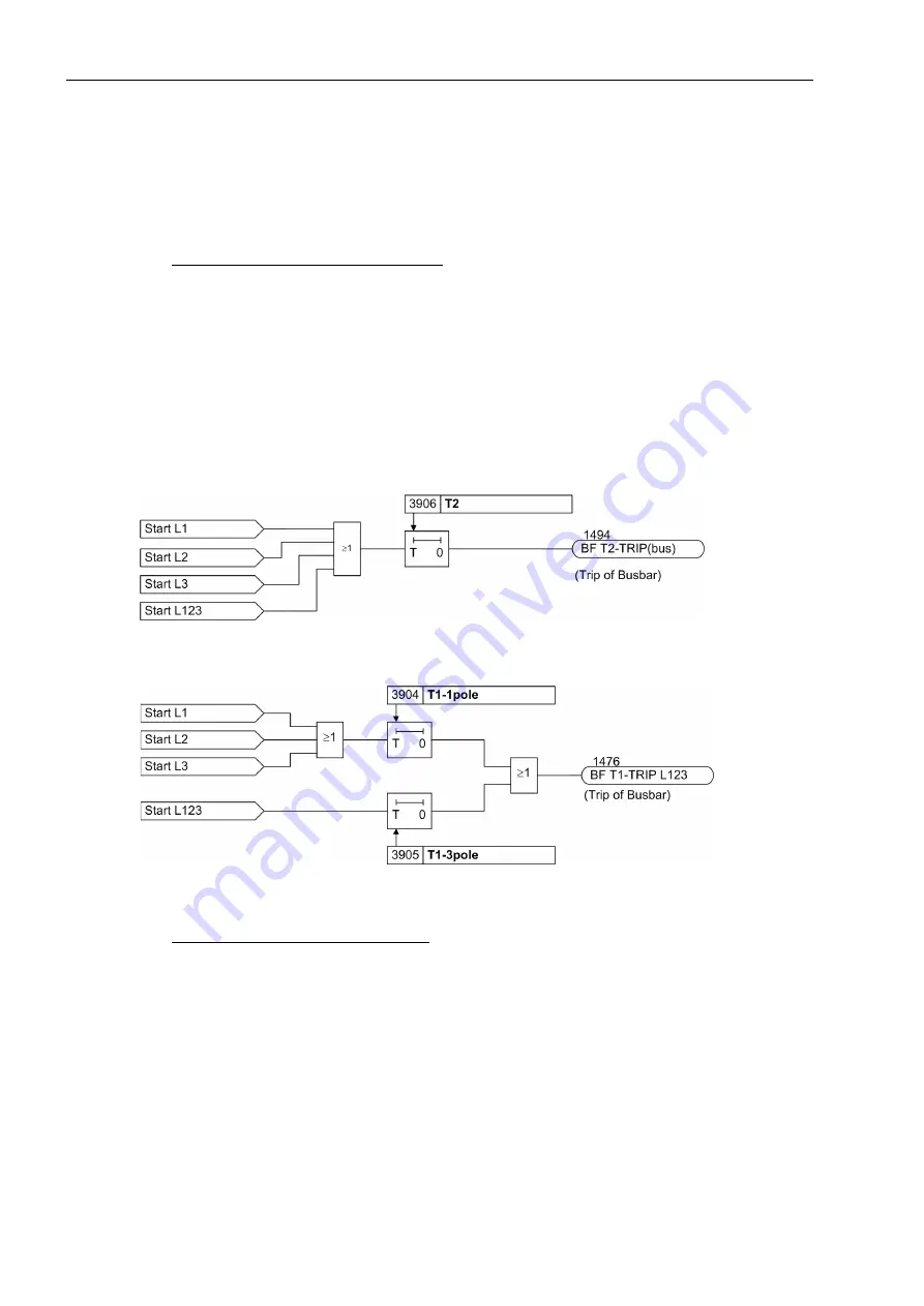
The simplest solution is to start the delay timer
T2
(Figure 2-192). The phase-segregated initiation signals are
omitted if the feeder protection always trips 3-pole or if the circuit breaker is not capable of 1-pole tripping.
If different delay times are required after a 1-pole trip or 3-pole trip it is possible to use the timer stages
T1-
1pole
and
T1-3pole
according to Figure 2-193.
Figure 2-192
Single-stage breaker failure protection with common phase initiation
Figure 2-193
Single-stage breaker failure protection with different delay times
With two-stage circuit breaker failure protection the trip command of the feeder protection is usually repeated,
after a first time stage, to the feeder circuit breaker, often via a second trip coil or set of trip coils, if the circuit
breaker has not responded to the original trip command. A second time stage monitors the response to this
repeated trip command and trips the circuit breakers of the relevant busbar section if the fault has not yet been
cleared after this second time.
For the first stage, a different delay
T1-1pole
can be set for 1-pole trip than for 3-pole trip by the feeder pro-
tection. Additionally, you can select (by setting parameter
1p-RETRIP (T1)
) whether this repeated trip should
be 1-pole or 3-pole. In case of a multi-pole tripping of the feeder protection,
T1-1pole
and
T1-3pole
are
started simultaneously. By means of
T1-3pole
, the tripping of the circuit breaker failure protection can be ac-
celerated in comparison to
T1-1pole
.
Содержание SIPROTEC
Страница 20: ...Contents SIPROTEC 7SD5 Manual C53000 G1176 C169 5 Release date 02 2011 20 ...
Страница 351: ...Functions 2 18 Synchronism and Voltage Check optional SIPROTEC 7SD5 Manual C53000 G1176 C169 5 Release date 02 2011 351 ...
Страница 494: ...Functions 2 27 Command Processing SIPROTEC 7SD5 Manual C53000 G1176 C169 5 Release date 02 2011 494 ...
Страница 640: ...Technical Data 4 27 Dimensions SIPROTEC 7SD5 Manual C53000 G1176 C169 5 Release date 02 2011 640 ...
Страница 657: ...Appendix A 2 Terminal Assignments SIPROTEC 7SD5 Manual C53000 G1176 C169 5 Release date 02 2011 657 7SD5 W ...
Страница 754: ...Appendix A 10 Measured Values SIPROTEC 7SD5 Manual C53000 G1176 C169 5 Release date 02 2011 754 ...
Страница 756: ...Literature SIPROTEC 7SD5 Manual C53000 G1176 C169 5 Release date 02 2011 756 ...
Страница 768: ...Glossary SIPROTEC 7SD5 Manual C53000 G1176 C169 5 Release date 02 2011 768 ...


