Functions
2.5 Distance Protection
SIPROTEC, 7SD5, Manual
C53000-G1176-C169-5, Release date 02.2011
157
Note
On long lines with small R/X ratio, care must be taken to ensure that the R reach of the zone settings is at least
about half of the associated X setting. This is especially important for zone Z1 and overreach zone Z1B in order
to achieve the shortest possible tripping times.
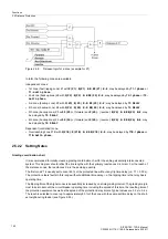
Independent Zones Z1 to Z6
By means of the parameter MODE =
Forward
or
Reverse
or
Non-Directional
, each zone can be set (ad-
dress
1601
Op. mode Z1
,
1611
Op. mode Z2
,
1621
Op. mode Z3
,
1631
Op. mode Z4
,
1641
Op. mode
Z5
and
1661
Op. mode Z6
). This allows any combination of graded zones - forward, reverse or non-direc-
tional -, for example on transformers, generators, or bus couplers. For the fifth and sixth zone, you can addi-
tionally set different reaches for forward and reverse. Zones that are not required are set to
Inactive
.
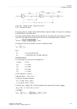
The values derived from the grading coordination chart are set for each of the required zones. The setting pa-
rameters are grouped for each zone. For the first zone these are the parameters
R(Z1) Ø-Ø
(address
1602
)
for the R intersection of the polygon applicable to phase-to-phase faults,
X(Z1)
(address
1603
) for the X in-
tersection (reach),
RE(Z1) Ø-E
(address
1604
) for the R intersection applicable to phase-to-earth faults and
delay time settings.
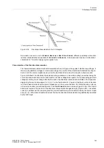
If a fault resistance at the fault location (arc, tower footing etc.) causes a voltage drop in the measured imped-
ance loop, the phase angle difference between this voltage and the measured loop current may shift the deter-
mined fault location in X direction. Parameter
1607
Zone Reduction
allows an inclination of the upper limit
of zone Z1 in the 1st quadrant (see Figure 2-52). This prevents spurious pickup of zone Z1 in the presence of
faults outside the protected area. Since a detailed calculation in this context can only apply for one specific
system and fault condition, and a virtually unlimited number of complex calculations would be required to de-
termine the setting, we suggest a simplified but well-proven method here:
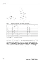
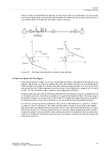
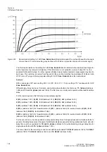
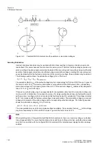
Figure 2-61
Equivalent circuit diagram for the recommended angle setting
Zone Reduction
.
The voltage drop at the fault location is:
U
F
= (
I
A
+
I
B
) · R
F
If
I
A
and
I
B
have equal phase, then U
F
and
I
A
have equal phase too. In this case the fault resistance R
F
does
not influence the measured X in the loop, and the
Zone Reduction
can be set to 0°.
In practice,
I
A
and
I
B
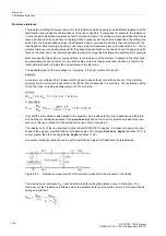
do not have equal phase; the difference results mostly from the phase difference between
U
A
and U
B
. This angle (also called load angle) is therefore used to determine the
Zone Reduction
angle.
Содержание SIPROTEC
Страница 20: ...Contents SIPROTEC 7SD5 Manual C53000 G1176 C169 5 Release date 02 2011 20 ...
Страница 351: ...Functions 2 18 Synchronism and Voltage Check optional SIPROTEC 7SD5 Manual C53000 G1176 C169 5 Release date 02 2011 351 ...
Страница 494: ...Functions 2 27 Command Processing SIPROTEC 7SD5 Manual C53000 G1176 C169 5 Release date 02 2011 494 ...
Страница 640: ...Technical Data 4 27 Dimensions SIPROTEC 7SD5 Manual C53000 G1176 C169 5 Release date 02 2011 640 ...
Страница 657: ...Appendix A 2 Terminal Assignments SIPROTEC 7SD5 Manual C53000 G1176 C169 5 Release date 02 2011 657 7SD5 W ...
Страница 754: ...Appendix A 10 Measured Values SIPROTEC 7SD5 Manual C53000 G1176 C169 5 Release date 02 2011 754 ...
Страница 756: ...Literature SIPROTEC 7SD5 Manual C53000 G1176 C169 5 Release date 02 2011 756 ...
Страница 768: ...Glossary SIPROTEC 7SD5 Manual C53000 G1176 C169 5 Release date 02 2011 768 ...


