


Functions
2.5 Distance Protection
SIPROTEC, 7SD5, Manual
C53000-G1176-C169-5, Release date 02.2011
172
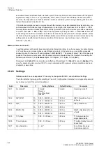
Independent Zones Z1 up to Z6
With the parameter MODE
Forward
or
Reverse
, each zone can be set (address
1701
Op. mode Z1
,
1711
Op. mode Z2
,
1721
Op. mode Z3
,
1731
Op. mode Z4
,
1741
Op. mode Z5
and
1761
Op. mode Z6
).
This allows any combination of forward or reverse graded zones. Zones that are not required are set
Inactive
.
The values derived from the grading coordination chart are set for each of the required zones. The setting pa-
rameters are grouped for each zone. For the first zone these are the parameters
ZR(Z1)
(address
1702
) spec-
ifying the impedance of the upper zenith of the MHO characteristic from the origin (reach), as well as the rele-
vant delay time settings.
Different delay times can be set for single- and multiple-phase faults in the first zone:
T1-1phase
(Address
1605
) and
T1-multi-phase
(address
1606
). The first zone is normally set to operate without additional time
delay.
For the remaining zones the following correspondingly applies:
ZR(Z2)
(address
1712
)
ZR(Z3)
(address
1722
)
ZR(Z4)
(address
1732
)
ZR(Z5)
(address
1742
)
ZR(Z6)
(address
1762
)
For the second zone it is also possible to set separate delay times for single-phase and multi-phase faults. In
general the delay times are set the same. If stability problems are expected during multi-phase faults, a shorter
delay time could be considered for
T2-multi-phase
(address
1616
) while tolerating a longer delay time for
single-phase faults with
T2-1phase
(address
1615
).
The zone timers for the remaining zones are set with the parameters
T3 DELAY
(address
1625
),
T4 DELAY
(address
1635
),
T5 DELAY
(address
1645
), and
T6 DELAY
(address
1665
).
If the device is provided with the capability to trip single-pole, single-pole tripping is then possible in the zones
Z1 and Z2. While single-pole tripping usually applies to single-phase faults in Z1 (if the remaining conditions
for single-pole tripping are satisfied), this may also be selected for the second zone with address
1617
Trip
1pole Z2
. Single pole tripping in zone 2 is only possible if this address is set to
Yes
. The default setting is
No
.
Note
For instantaneous tripping (undelayed) in the forward direction, the first zone
Z1
should always be used, as
only the Z1 and Z1B are guaranteed to trip with the shortest operating time of the device. The further zones
should be used sequentially for grading in the forward direction.
If instantaneous tripping (undelayed) is required in the reverse direction, the zone
Z3
should be used for this
purpose, as only this zone ensures instantaneous pickup with the shortest device operating time for faults in
the reverse direction. This setting is also recommended in teleprotection
BLOCKING
schemes.
With the binary input indications No. 3619
„>BLOCK Z4 Ph-E“
, No. 3620
„>BLOCK Z5 Ph-E“
, and No. 3622
„>BLOCK Z6 Ph-E“
, the zones Z4, Z5, and Z6 for phase-to-earth loops may be blocked. To block these zones
permanently for phase-to-earth loops, these binary input indications must be set permanently to the logic value
of 1 via CFC.
Содержание SIPROTEC
Страница 20: ...Contents SIPROTEC 7SD5 Manual C53000 G1176 C169 5 Release date 02 2011 20 ...
Страница 351: ...Functions 2 18 Synchronism and Voltage Check optional SIPROTEC 7SD5 Manual C53000 G1176 C169 5 Release date 02 2011 351 ...
Страница 494: ...Functions 2 27 Command Processing SIPROTEC 7SD5 Manual C53000 G1176 C169 5 Release date 02 2011 494 ...
Страница 640: ...Technical Data 4 27 Dimensions SIPROTEC 7SD5 Manual C53000 G1176 C169 5 Release date 02 2011 640 ...
Страница 657: ...Appendix A 2 Terminal Assignments SIPROTEC 7SD5 Manual C53000 G1176 C169 5 Release date 02 2011 657 7SD5 W ...
Страница 754: ...Appendix A 10 Measured Values SIPROTEC 7SD5 Manual C53000 G1176 C169 5 Release date 02 2011 754 ...
Страница 756: ...Literature SIPROTEC 7SD5 Manual C53000 G1176 C169 5 Release date 02 2011 756 ...
Страница 768: ...Glossary SIPROTEC 7SD5 Manual C53000 G1176 C169 5 Release date 02 2011 768 ...