


Functions
2.5 Distance Protection
SIPROTEC, 7SD5, Manual
C53000-G1176-C169-5, Release date 02.2011
140
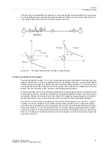
Angular dependence is not needed in the majority of cases. Then the voltage-dependent section b is valid and
results in the characteristic a-b-c. When controlling with Uphe the voltages for phase-to-earth current are in-
serted in address
1912
Uph-e (I>>)
and
1913
Uph-e (I>)
for the voltage-dependent section b. When
controlling with Uphph the voltages for phase-to-phase are set in address
1914
Uph-ph (I>>)
and
1915
Uph-ph (I>)
. The relevant settings are determined according to the pickup mode (see above).
The characteristic has to be set such that it is just below the minimum expected voltage at the maximum ex-
pected load current. If in doubt, check the pickup conditions in accordance with the U/
I
characteristic.
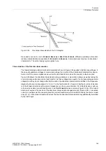
Angular dependence
If a distinction between short-circuit and load conditions is not always possible using the U/
I
characteristic,
which is independent of the phase angle, the angular dependent sections d-e can additionally be used. This is
required for long lines or line sections with intermediate infeed in combination with small source impedances.
Then the local measured voltage will only drop to a small extent in the event of a short-circuit at the line end or
in the back-up range of the distance protection so that the phase angle between current and voltage is required
as an additional criterion for fault detection.
The parameters
Iphi>
(address
1916
) and
Uph-e (Iphi>)
(address
1917
) or
Uph-ph (Iphi>)
(address
1918
) determine the characteristic in the range of large angles
ϕ
SC
, i.e. in the short-circuit angular range. The
threshold angles themselves, which define the short-circuit angle range
ϕ
SC
, are set in address
1920
ϕ
>
and
1921
ϕ
<
. The short-circuit angle range
ϕ
SC
is located between these two angles. Here, too, the required voltage
settings according to the pickup mode (see above) are relevant.
The characteristic for the load angle range has to be set in a way that is just below the minimum expected op-
erating voltage at the maximum expected load current. In the range of the short-circuit angles
ϕ
SC
it must be
ensured that load current may not cause pickup in this area. If reactive power has to be transferred via this line,
it must be ensured that the maximum reactive current at minimum operating voltage is not within the pickup
range, i.e. the short-circuit angle range
ϕ
SC
. If in doubt, check the pickup conditions in accordance with the U/
I
/
ϕ
characteristic. An arithmetic short-circuit calculation is recommended for extensive networks.
The lower threshold angle
ϕ
>
(address
1920
) should be between the load angle and the short-circuit angle.
Therefore it must be set smaller than the line angle
ϕ
L
= arctan (X
L
/R
L
) (approx. 10° to 20°). Subsequently, you
should check that the angle is not exceeded during load conditions. If this is the case, for instance because the
reactive power has to be transferred via this line, it must be ensured that the parameters of the voltage-depen-
dent segment d, that is
Iphi>
and
Uph-e (Iphi>)
or
Uph-ph (Iphi>)
rule out a pickup as the result of
reactive power (see above).
The upper threshold angle
ϕ
<
(address
1921
) is not critical. 100° to 120° should be sufficient in all cases.
Angular dependence, i.e. increasing the sensitivity for a large short-circuit angle with sections d and e in the
characteristic, can be limited to the forward direction (line direction) using address
1919
EFFECT
ϕ
. In this
case,
EFFECT
ϕ
is set to
Forward
. Otherwise
EFFECT
ϕ
=
forward&reverse
is retained. This parameter
can only be changed in DIGSI at
Display Additional Settings
.
Содержание SIPROTEC
Страница 20: ...Contents SIPROTEC 7SD5 Manual C53000 G1176 C169 5 Release date 02 2011 20 ...
Страница 351: ...Functions 2 18 Synchronism and Voltage Check optional SIPROTEC 7SD5 Manual C53000 G1176 C169 5 Release date 02 2011 351 ...
Страница 494: ...Functions 2 27 Command Processing SIPROTEC 7SD5 Manual C53000 G1176 C169 5 Release date 02 2011 494 ...
Страница 640: ...Technical Data 4 27 Dimensions SIPROTEC 7SD5 Manual C53000 G1176 C169 5 Release date 02 2011 640 ...
Страница 657: ...Appendix A 2 Terminal Assignments SIPROTEC 7SD5 Manual C53000 G1176 C169 5 Release date 02 2011 657 7SD5 W ...
Страница 754: ...Appendix A 10 Measured Values SIPROTEC 7SD5 Manual C53000 G1176 C169 5 Release date 02 2011 754 ...
Страница 756: ...Literature SIPROTEC 7SD5 Manual C53000 G1176 C169 5 Release date 02 2011 756 ...
Страница 768: ...Glossary SIPROTEC 7SD5 Manual C53000 G1176 C169 5 Release date 02 2011 768 ...