Configuration
5-3
7SJ63 Manual
C53000-G1140-C120-1
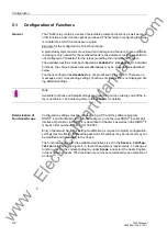
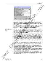
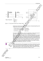
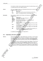
Figure 5-1
Device Configuration Dialog Box in (example) DIGSI
®
4
Before closing the dialog box, transfer the modified functional setting to the relay by
clicking on the item
',*6,
→
'HYLFH
. The data is stored in the relay in a Non-Volatile
Memory Buffer.
The configured functional scope can be
viewed
from the front display of the relay itself,
but cannot be modified. The settings associated with the functional scope can be
found in the
0$,10(18
under
→
6HWWLQJV
→
'HYLFH&RQILJ
.
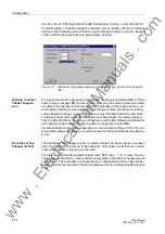
Special Character-
istics
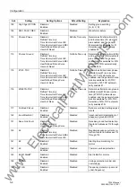
If use of the setting group change function is desired, address
should be set to
(QDEOHG
. In this case, up to four different groups of settings (see Chapter 6) may be
entered quickly and easily during device operation. Only one setting group may be se-
lected and used if the setting is
'LVDEOHG
.
For the relay elements associated with non-directional overcurrent protection (both
phase and ground ), various tripping characteristics may be selected at the addresses
(phase) and
(ground). If only the definite time characteristic is desired,
then
'HILQLWH7LPHRQO\
should be selected. Additionally, depending on the relay
model ordered, various inverse time characteristics are available (based on either IEC
standards or ANSI standards), or user defined characteristics may be specified. A
user defined characteristic can include both a tripping and a reset characteristic. Non-
directional overcurrent protection may be defeated during configuration by selecting
'LVDEOHG
.
For directional overcurrent protection, the same information can be entered at ad-
dresses
(phase) and
(ground) that was entered for the non-directional
overcurrent protection at addresses
and
.
For sensitive ground fault protection, address
is used to specify whether the
function should be disabled, enabled with definite time tripping characteristics only, or
enabled with a user defined inverse time characteristic.
For negative sequence protection, address
is used to specify whether the func-
tion should be disabled, enabled with definite time tripping characteristics only, or en-
abled with an ANSI inverse time characteristic.
For trip circuit monitoring, address
7ULS&W6XSY
is used to specify wheth-
er two binary inputs should be utilized, one binary input should be utilized, or the func-
tion should be disabled.
www
. ElectricalPartManuals
. com
Содержание siprotec 7SJ63
Страница 16: ...xiv 7SJ63 Instruction Manual C53000 G1140 C120 1 w w w E l e c t r i c a l P a r t M a n u a l s c o m ...
Страница 28: ...Introduction 1 12 7SJ63 Manual C53000 G1140 C120 1 w w w E l e c t r i c a l P a r t M a n u a l s c o m ...
Страница 112: ...SIPROTEC 4 Devices 4 38 7SJ63 Manual C53000 G1140 C120 1 w w w E l e c t r i c a l P a r t M a n u a l s c o m ...
Страница 346: ...Functions 6 182 7SJ63 Manual C53000 G1140 C120 1 w w w E l e c t r i c a l P a r t M a n u a l s c o m ...
Страница 494: ...Technical Data 10 48 7SJ63 Manual C53000 G1140 C120 1 w w w E l e c t r i c a l P a r t M a n u a l s c o m ...
Страница 604: ...Index Index 6 7SJ63 Instruction Manual C53000 G1140 C120 1 w w w E l e c t r i c a l P a r t M a n u a l s c o m ...


