Hardware and Connections
2-21
7SJ63 Manual
C53000-G1140-C120-1
2.3
Version of 7SJ63 with a Detached Operator Panel
The numerical, multi-functional, SIPROTEC
®
7SJ63 with a detached operator panel
is intended for installation in a low-voltage compartment. The device consists of an op-
erator panel for installation in a mounting plate, and a 7XP20 case with housing size
1
/
2
or
1
/
1
(based on 19 inches) that contains the major printed circuit boards and ter-
minals, for installation on a mounting plate.
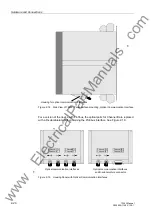
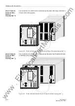
The operator panel is connected to the housing with a 7.2 ft (2.2 m), 68-pin cable. The
cable is fully assembled, and is part of the operator panel. A 68-pin connector is in-
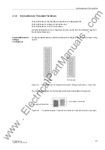
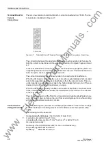
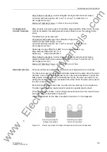
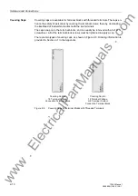
cluded for interfacing with the housing. See Figures 2-20 and 2-21.
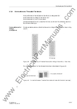
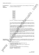
Threaded terminals and plug-in terminals are available.
2.3.1
Construction
Main Housing
The main housing consists of a case, a rear panel dependent upon the ordering num-
ber of the device, and a front cover without operating and display elements. Mats with
guide rails are mounted on the top and the bottom of the interior of the case. The guide
rails enable the printed circuit boards to be properly installed. The guide rails also sup-
port the boards while they are in-place. Each guide rail has a visible number, from 1
to 42, indicating the installation locations of the printed circuit boards. The printed cir-
cuit boards are inter-connected with ribbon cables and plug connectors. The terminals
for connecting the 7SJ63 to external equipment are on the rear panel, which is bolted
to the housing.
Nameplate stickers, which show important information such as the power supply rat-
ing, nominal current rating, and ordering number (MLFB), are located on the top of the
main housing and the interior of the device front cover.
Angle strips attached to the top and the bottom of the main housing are provided for
mounting purposes. Three holes are in each angle strip for a device with housing size
1
/
2
, and five holes are provided for a device with housing size
1
/
1
.
Operator Panel
The operator panel consists of a front cover and a housing. The cover contains a flat
keypad with the operating and display elements necessary to operate the 7SJ63. The
cable for interfacing with the main housing is connected to the keypad via plug con-
nectors.
Slotted holes behind the four caps at the corners of the front cover are provided for
mounting the operator panel to a plate with appropriate screws.
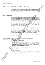
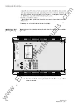
The significance of the operating and display elements on the cover is given in the in-
formation related to Figure 2-1.
www
. ElectricalPartManuals
. com
Содержание siprotec 7SJ63
Страница 16: ...xiv 7SJ63 Instruction Manual C53000 G1140 C120 1 w w w E l e c t r i c a l P a r t M a n u a l s c o m ...
Страница 28: ...Introduction 1 12 7SJ63 Manual C53000 G1140 C120 1 w w w E l e c t r i c a l P a r t M a n u a l s c o m ...
Страница 112: ...SIPROTEC 4 Devices 4 38 7SJ63 Manual C53000 G1140 C120 1 w w w E l e c t r i c a l P a r t M a n u a l s c o m ...
Страница 346: ...Functions 6 182 7SJ63 Manual C53000 G1140 C120 1 w w w E l e c t r i c a l P a r t M a n u a l s c o m ...
Страница 494: ...Technical Data 10 48 7SJ63 Manual C53000 G1140 C120 1 w w w E l e c t r i c a l P a r t M a n u a l s c o m ...
Страница 604: ...Index Index 6 7SJ63 Instruction Manual C53000 G1140 C120 1 w w w E l e c t r i c a l P a r t M a n u a l s c o m ...

