Functions
6-57
7SJ63 Manual
C53000-G1140-C120-1
6.3.2.4
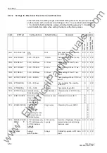
Programming Settings for Directional Overcurrent Ground Protection
General
The functions associated with time-overcurrent protection were established during
configuration of protective functions (Section 5.1) at address
1172&
. If
address
was set to
'HILQLWH7LPH2QO\
, then only the settings for the defi-
nite-time elements are available.
At address
)&71172&
, directional ground time-overcurrent protection
may be switched
21
or
2))
independent of the directional phase time-overcurrent pro-
tection.
Pickup values, time delays, and characteristic curves for ground protection are set
separately from the pickup values, time delays and characteristic curves associated
with directional phase protection. Because of this, relay coordination for ground faults
is independent of relay coordination for phase faults, and more sensitive settings can
often be applied to directional ground protection.
67N-2 Relay
Element
The pickup and delay of the 67N-2 relay element are set at addresses
1
3,&.83
and
1'(/$<
respectively. The same considerations apply for
these settings as did for 67-2 settings discussed earlier.
The delay set at address
is in addition to the 67N-2 pickup time. The delay of
the 67N-2 element may be set to
∞
. The 67N-2 element will then pickup and generate
a message, but will never trip. If the 67N-2 element is not required at all, then the pick-
up value should be set to
∞
, thus preventing pickup, trip, and the generation of a mes-
sage.
67N-1 Relay
Element
The pickup value of the 67N-1 relay element (set at address
13,&.83
)
should be set below the minimum anticipated ground fault current in the relay zone of
protection.
If the 7SJ63 relay is used to protect transformers or motors with large inrush currents,
the inrush restraint feature may be used to prevent a false trip of the 67N-1 relay ele-
ment. The configuration data for the inrush restraint feature is programmed at address
block 22 (see Subsection 6.5.2).
The delay of the 67N-1 element is set at address
1'(/$<
and should be
based on system coordination requirements.
The delay set at address
is in addition to the 67N-1 pickup time. The delay of
the 67N-1 element may be set to
∞
. The 67N-1 element will then pickup and generate
a message, but will never trip. If the 67N-1 element is not required at all, then the pick-
up value should be set to
∞
thus preventing pickup, trip, and the generation of a mes-
sage.
67N-TOC with IEC
Curves
Pickup of the 67N-TOC relay element will occur for currents greater than or equal to
110% of the 67N-TOC element’s pickup value, and may or may not occur for currents
between 100% and 110% of the 67N-TOC element’s pickup value. Dropout of the 51N
relay element occurs when the current decreases to 95% of the 67N-TOC element’s
pickup value.
The pickup value of the 67N-TOC element is set at address
172&3,&.83
.
As is the case for the 67N-1 relay element, the pickup value of the 67N-TOC relay el-
ement should be set below the minimum anticipated ground fault current in the relay
zone of protection.
The 67N-TOC element time multiplication factor is set at address
172&7
',$/
and should be based on system coordination requirements.
www
. ElectricalPartManuals
. com
Содержание siprotec 7SJ63
Страница 16: ...xiv 7SJ63 Instruction Manual C53000 G1140 C120 1 w w w E l e c t r i c a l P a r t M a n u a l s c o m ...
Страница 28: ...Introduction 1 12 7SJ63 Manual C53000 G1140 C120 1 w w w E l e c t r i c a l P a r t M a n u a l s c o m ...
Страница 112: ...SIPROTEC 4 Devices 4 38 7SJ63 Manual C53000 G1140 C120 1 w w w E l e c t r i c a l P a r t M a n u a l s c o m ...
Страница 346: ...Functions 6 182 7SJ63 Manual C53000 G1140 C120 1 w w w E l e c t r i c a l P a r t M a n u a l s c o m ...
Страница 494: ...Technical Data 10 48 7SJ63 Manual C53000 G1140 C120 1 w w w E l e c t r i c a l P a r t M a n u a l s c o m ...
Страница 604: ...Index Index 6 7SJ63 Instruction Manual C53000 G1140 C120 1 w w w E l e c t r i c a l P a r t M a n u a l s c o m ...

