Functions
6-79
7SJ63 Manual
C53000-G1140-C120-1
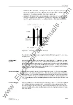
Figure 6-37
Location of Ground Connection based on Direction Indicators in a Looped Sys-
tem
6.6.2
Programming Settings
General Settings
During configuration of protective functions, address
6HQV*QG)DXOW
should
be set to
'HILQLWH7LPHRQO\
if the inverse characteristic is not required,
8VHU
'HILQHG3LFNXS&XUYH
if both a definite time and inverse time characteristic are
required, and
'LVDEOHG
if the function is not required at all.
Also, during configuration, address
97&RQQHFWLRQ
determines how the volt-
age transformers are connected (phase-to-ground or phase-to-phase), and addresses
9SK9GHOWD
and
&71V&73K
contain the conforming factors for zero
sequence ground voltage and the zero sequence current inputs.
Sensitive ground fault detection may be switched
21
,
2))
, or to
0HVVDJH2QO\
, at
address
6HQV*QG)DXOW
. If sensitive ground fault protection is switched
21
,
both tripping and message reporting is possible.
Angular Error
Compensation
Addresses
through
only apply to compensated systems which utilize Pe-
tersen coils. Since the utilization of compensated systems is primarily limited to Euro-
pean practices, a detailed explanation of these settings is beyond the scope of this
particular instruction manual. In the rare event that this protective relay is utilized in a
compensated system, the reader should contact Siemens Power T&D for more infor-
mation regarding application of the 7SJ63 relay in a compensated system.
Determination of
the Phase with a
Ground Connection
The phase connected to ground may be identified in an ungrounded system, if the de-
vice is supplied by three voltage transformers connected in a grounded-wye configu-
ration. The phase whose voltage lies below the minimum voltage setting at address
93+0,1
is identified as the phase connected to ground as long as the other
two phase voltages simultaneously exceed the maximum voltage setting at address
93+0$;
. The setting at address
must be set less than the minimum al-
lowable phase-to-ground voltage. A typical setting for this address would be 40 V. The
maximum voltage setting at address
must be greater than the minimum allow-
able phase-to-ground voltage, but less than the minimum phase-to-phase voltage. For
V
N
= 100 V, approximately 75 V is a typical setting. These settings have no signifi-
cance in a grounded system.
Displacement Volt-
age V
0
or 3V
0
The pickup due to displacement voltage is set at address
9*1'
if V
0
is
measured or address
9*1'
is 3V
0
is calculated. Pickup of the voltage el-
www
. ElectricalPartManuals
. com
Содержание siprotec 7SJ63
Страница 16: ...xiv 7SJ63 Instruction Manual C53000 G1140 C120 1 w w w E l e c t r i c a l P a r t M a n u a l s c o m ...
Страница 28: ...Introduction 1 12 7SJ63 Manual C53000 G1140 C120 1 w w w E l e c t r i c a l P a r t M a n u a l s c o m ...
Страница 112: ...SIPROTEC 4 Devices 4 38 7SJ63 Manual C53000 G1140 C120 1 w w w E l e c t r i c a l P a r t M a n u a l s c o m ...
Страница 346: ...Functions 6 182 7SJ63 Manual C53000 G1140 C120 1 w w w E l e c t r i c a l P a r t M a n u a l s c o m ...
Страница 494: ...Technical Data 10 48 7SJ63 Manual C53000 G1140 C120 1 w w w E l e c t r i c a l P a r t M a n u a l s c o m ...
Страница 604: ...Index Index 6 7SJ63 Instruction Manual C53000 G1140 C120 1 w w w E l e c t r i c a l P a r t M a n u a l s c o m ...


